


CHAPTER 2
CHAPTER 2
Installation
Inspecting the Equipment
If any FALCON
®
equipment has been damaged during shipment, keep
the shipping cartons and packing materials for the carrier and file a
claim for shipping damage. If you discover damage after acceptance,
file a claim for concealed damage.
To file a claim for shipping damage or concealed damage: 1) File with
the carrier within 15 days of receipt of the equipment; 2) Send a copy
of the damage claim within 15 days to the Falcon
®
Service Department.
ED Setup
1. Verify that the following is included in the ED shipping carton:
ED Frequency Converter & UPS, Owner's Guide.
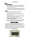
2. Verify that the ED unit is configured for the proper input/output
voltage. This information is stated on the nameplate label located on
the rear panel of the unit.
3. Select a suitable location for the ED, near enough to the computer or
equipment to allow connection of the equipment power plugs to the
receptacles located on the rear panel of the ED.
4. DO NOT BLOCK UPS AIR VENTS. THE UPS MUST NOT BE
INSTALLED IN AN ENCLOSED AREA.
5. Connect the equipment to be powered to the ED output receptacles
located on the rear panel. Verify that the connected equipment does
not exceed the rated output (in watts) of the ED Series unit
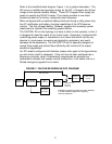
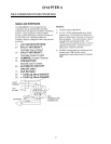
This ED model is designed for input and output hardwire connections. Two
conduit connector holes are provided on the lower portion of the rear panel.
The hardwire terminal block is located inside the ED unit and can be
accessed by removing the (16) screws securing the units top cover. Remove
the top cover: the terminal block is located on the upper left side of the units
center panel. Pay special attention to the ED input voltage configuration and
verify the input voltage is correct prior to hardwiring the unit. Make the input
and output connections per the picture below.
USE COPPER WIRE ONLY.
IMPORTANT
4