


The supplied Falcon RS-232 interface cable pin designations are as follows:
The computer RS-232 Port settings should be set to the following:
7.3 Optional Remote Emergency Power Off (REPO)
A two-pin REPO connector (green connector) is located on the UPS module rear panel. The connector is
shipped with no jumper wire installed, and is a normally open interface requiring a CLOSED EPO connection
to initiate EPO UPS shutdown.
Upon receiving the remote EPO switch contact closure, the UPS will immediately turn off it’s inverter and
bypass outputs, in addition to placing the UPS into an “OFF” state and sounding an audible alarm. “OFF” and
“EPO” will be alternately displayed on the LCD panel.
After removal of the EPO contact closure, the UPS must be completely shut down and restarted to clear the
EPO condition.
7.4 Optional Communications Interface Board Details
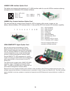
UA88380 Second RS-232 Interface Option Board
This communications board supports the connection of a second RS-232 DB-9 connection to the UPS, in
addition to providing (1) two-pin EPO interface connector. The DB-9 pinout is identical to the standard DB-9
RS-232 interface found on the UPS rear panel.
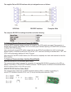
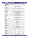
UA88381 RS-485 Interface Option Board
This communications board has (1) RS485 standard interface (CN2), in addition to providing (1)
two-pin EPO interface connector (CN1), and (1) two-pin remote power connector (CN3).
33
1
23
12
CN2
CN3
Pin 1 - Ground
Pin 2 - A/Data+
Pin 3 - B.Data-
Pin 1 - AC+
Pin 2 - AC-
12
CN1
Pin 1 - REPO 1
Pin 2 - REPO 2
UPS Side RS-232C Interface Computer Side