


6
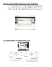
g. One Local Maintenance Bypass Switch. The switch is located on the transformer module rear panel
and provides a manual means of placing the UPS into bypass mode to allow for servicing to be performed on
the UPS and battery modules.
2.0 FN RACKMOUNT UPS CIRCUIT DESCRIPTIONS
Galvanically Isolated Output
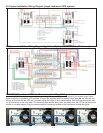
The FN -2TXI output isolation transformer module provides a galvanically isolated, 120/240Vac, hardwire out-
put. To meet UL and code requirements, a dedicated electrical panel should be provided by your electrical
contractor or electrician. The FN -2TXI output configuration can be configured for a 120Vac, 208, 220, 230, or
240Vac output. It may also be configured for a dual voltage or 120/240Vac split-phase hardwire output. This
configuration allows for the use of a standard electrical panel and readily available branch rated circuit break-
ers It also simplifies the distribution to 240Vac and 120Vac loads. The outputs of up to four FN -2TXI units
may be connected in parallel. Please refer to pages 12-13 of this manual for wiring details.
Additionally, the FN galvanic output isolation in conjunction with a derived neutral greatly reduces common
mode noise and ground loops.
Input & Power Factor Correction
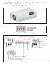
All FN rackmount models require a 2 wire plus ground type 208-240Vac power source, at 50 or 60Hz. Each
UPS module input must be connected to a dedicated circuit having a branch rated circuit breaker. If multiple
FN units are to be connected in parallel, care must be taken to verify the source electrical panel has enough
capacity. It must be rated to supply the total input power requirements of all FN Series units being connected,
including all optional extended battery chargers, in addition to any other circuits that may be connected to the
panel. Please have your electrical contractor review the FN datasheet located at the end of this manual and
perform a site survey several weeks in advance of the installation date.
While the FN Series UPS is operating from the utility power, it’s internal power factor correction circuit
converts utility AC power into regulated DC power for inverter use. The circuit also corrects the input current
to maintain the phase relationships between both current and voltage sine waveforms. this also minimize the
amount of current distortion that is reflected back to the utility line.
DC/DC Converter
The DC/DC converter utilizes energy from the batteries and boosts up the DC voltage to a level required by
the inverter. This allows the inverter to operate continuously at optimum efficiency and voltage. The converter
incorporates a patented circuit which reduces the amount of ripple current and EMI interference to the battery,
increasing the overall battery life.
DC/AC Inverter
In utility mode operation, the inverter utilizes the regulated DC output and converts it back into clean,
regulated sinewave AC power. When utility power fails, the inverter will receive its energy from the battery
through the DC/DC converter. In both modes of operation, the UPS inverter is online and continuously
generates clean, regulated AC output power to the load. The IGBT, PWM inverter is of a very robust design
and produces a pure sinewave output with a +/-2% voltage regulation. Having a very low output impedance, it
can supply the high current demands of high inrush and non-linear loads.