


Installation
CER International bv 11
Hardware installation
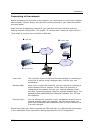
You communicate with the controller over the Ethernet network. In this part of the
chapter, you'll learn about the unit itself and how and where to connect it. There are no
configurable parts inside. Everything is controlled and configured by the software.
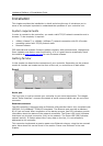
Physical installation
You can use the controller in several places, depending on your needs:
• freely (unfixed) on your desktop with the included adhesive plastic bumpers.
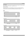
• fixed to a DIN-rail using the supplied DIN-rail clips. These can be inserted into the
holes in the case. Be sure to position the rebated joints at the outside of the
Controller for easy removal of the case from the DIN-rail in the future.
• if outdoor option: fixed to a wall or 1" mast using the waterproof NEMA-67 outdoor
case
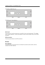
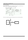
Connecting power
The controller requires power of a single 7-18VDC. The power consumption is rated at
12VDC/0.25A
TYP
and 12VDC/0.4A
MAX
. This can be applied using a Power adaptor or Power
Over Ethernet.
Power adaptor
Follow these steps to connect the controller to your power supply:
1. Make sure the power supply is unplugged
2. Connect the DC jack to your controller
Now you can safely plug in your power supply. Notice that the PWR indicator lights up.
Warning! Always disconnect the power cord from the controller when you
are (dis)mounting devices, interfaces or sensors. Do not (dis)connect
while the power is on. A sudden rush of power can damage sensitive
electronic components.
Warning! The controller has very low ESR input capacitors.
To avoid arcing, please plug in the DC jack to the controller first, then
plug the AC adapter into mains.