


Serial interfaces
CER International bv 23
Serial interface
In this part of the installation manual, you will learn some basics of serial
communication, the hardware involved and how the CER controller connects to your RS-
232 device.
RS-232
The RS-232c standard
The RS-232 standard (RS stands for recommended standards) was published first in
1969 by the EIA (Electronic Industries Association). It was originally drawn up to specify
the connections between terminals and modems. It specifies the electrical characteristics
of circuits between the devices and gives names and numbers to the wires.
RS-232-C is the third - and most common - version of the standard so it is often simply
referred to as RS-232 (without the 'c'). The combination of ITU-T's (formerly CCITT) V.24
and V.28 standards are equivalent to EIA-RS-232-C. In short: V.24+V.28 RS-232.
The characteristics of the RS-232c protocol are as follows:
S point-to-point communication (full duplex)
S maximum line length between sender and receiver 15 meters (50 feet).
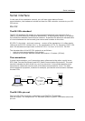
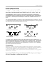
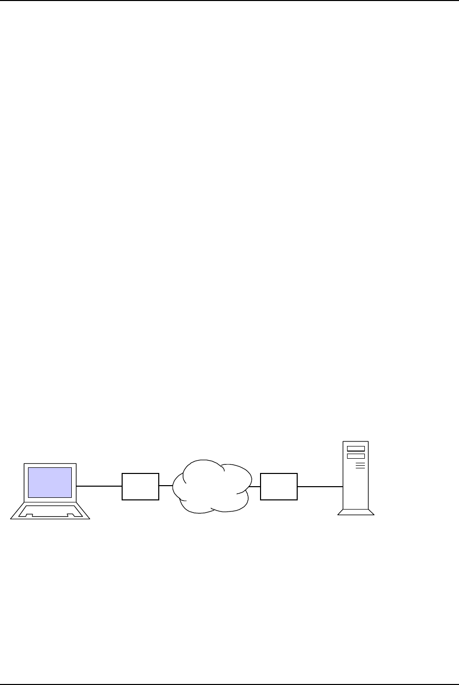
The connections
In serial communication, you'll encounter many references to the rather cryptic terms
DTE (Data Terminal Equipment) and DCE (Data Communication Equipment). The word
terminal indicates the end of the line, as in bus terminal. In the phrase data terminal
equipment it means the extreme ends of the data communications circuit. The data
communications equipment, modems for example, provide the communication between
the two DTEs.
DCE
TELEPHONE
NETWORK
DCE
DTE
Computer
RS-232c
RS-232c
DTE
Terminal
Modem
Modem
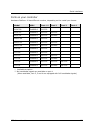
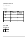
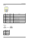
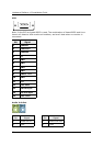
The RS-232c pin-out
The 9-pin RS-232c connector is described in the EIA/TIA-574 standard.
See the chapter “Pin Assignments” for Hardware platform specific information about the
pin-out.