


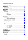
Hardware Platform 10 Installation Guide
8
Installation
This chapter explains the installation in detail and along the way it introduces you to
some of the concepts important to understand the operation of your controller unit.
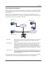
System requirements
In order to connect to the controller, you need a valid TCP/IP network connection and a
browser. To be complete, it requires:
• 10Mbit (10base-T) or 100Mbit (100base-T) network connection with RJ-45 socket
• operating system with TCP/IP protocol stack
• Internet browser
CER International releases firmware updates regularly with enhancements, changes and
fixes. Updates may feature new functionality, so it is a good idea to occasionally check
the website at http://www.cer.com for new firmware releases.
Getting familiar
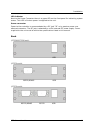
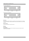
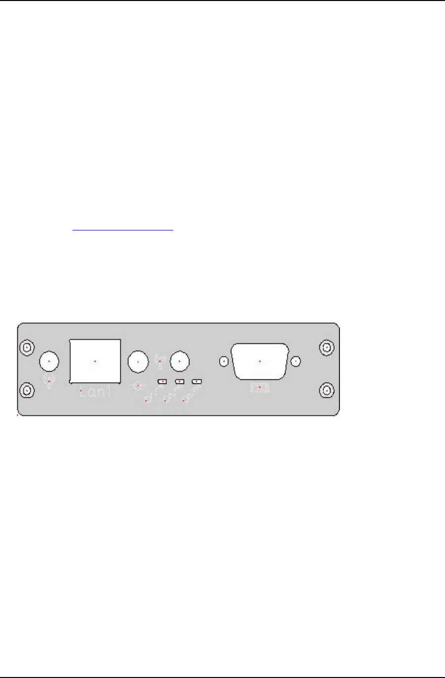
In this chapter we describe the connectors of your controller. Depending on the product
model all controls are located on the front of the unit, or controls are on both sides:
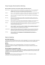
Front
Ethernet Power RS232
Serial port
The 9-pin port is used to connect your controller to your serial equipment. The chapter
called "Serial Interface" uncovers the details of serial communication and pin-out of the
connector.
Ethernet connector
The CER controller is equipped with an Ethernet LAN controller that is fully compliant with
IEEE 802.3 10/100Base-T CSMA/CD standards. The Ethernet port provides a standard
RJ-45 jack on board. After completion of the startup process, two LED indicators provide
information about the status of the network connection. The Green LED (right) indicates
that there is a physical connection (link) to the network. The Green LED (left) indicates
network activity. It flashes when there is any data on the line; it's not necessarily
addressed to the controller.
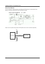
This connector implements a passive power over Ethernet scheme, using the two unused
pairs. More about this can be found in the section ‘Power over Ethernet’ in the next
chapter.