


Start-up guide
Page 5 FS-X20 Series FieldServer Start-up Guide (07-2005)
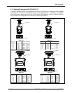
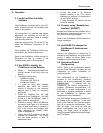
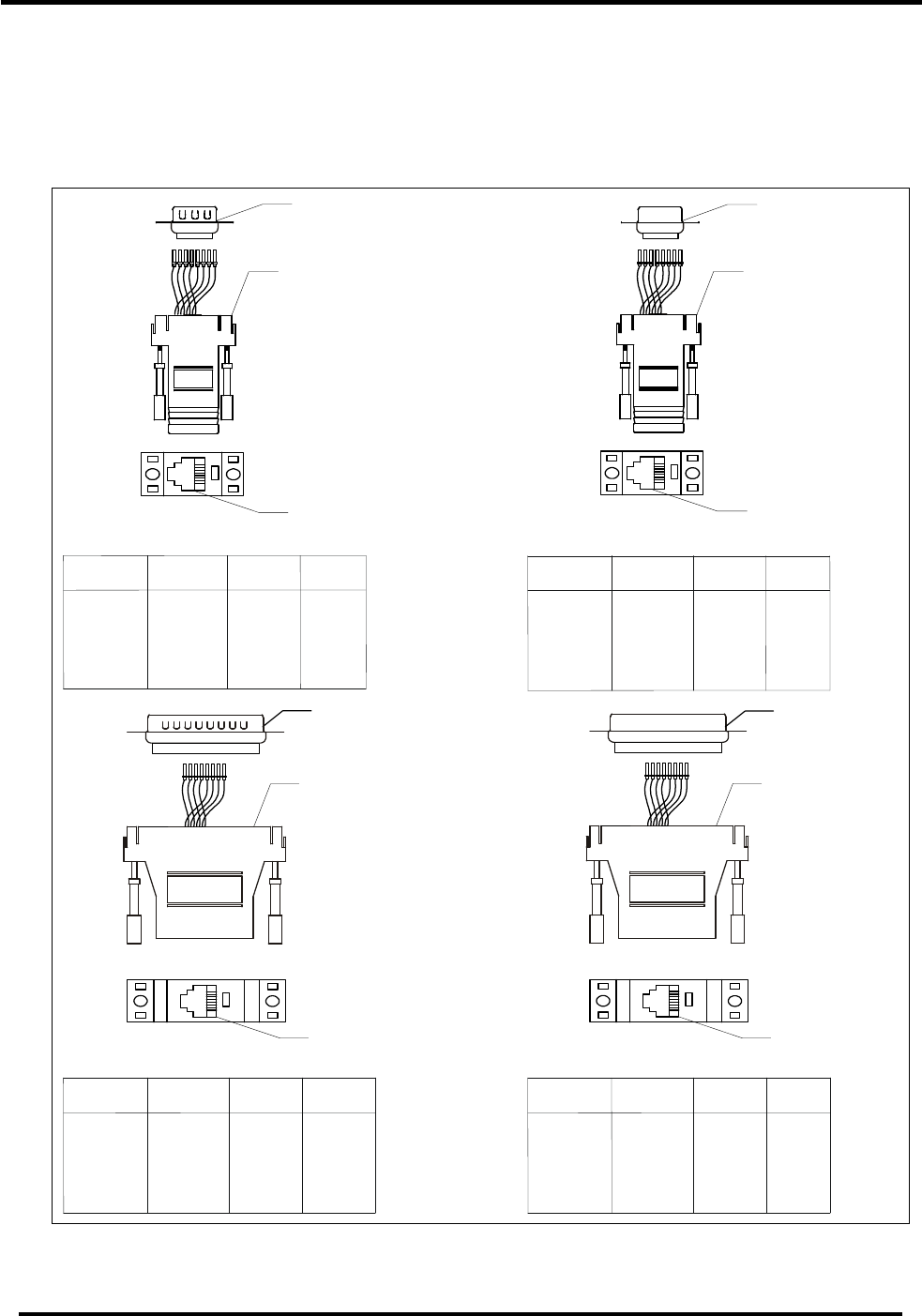
2.4. Supplied Connector Kit (FS-8915-11)
In order to facilitate RS-232 communications on the RJ-45 RS-232 port, a connector kit is supplied
containing one of each of the connectors shown in the diagram below. The tables in the diagram
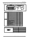
show the functions applied to each of the RJ-45 pins by the FieldServer to assist in determination of
the required pinout configuration for connection to the third party device.
8
1
RJ45
DB9M
FS-8917-03
8
1
RJ45
DB9F
FS-8917-02
DB25M
8
1
RJ45
FS-8917-01
8
1
RJ45
DB25F
FS-8917-04
Figure 2-4: FieldServer Connector Reference
RX
CTS
DSR
GND
GND
DTR
RTS
TX
RJ45-01
RJ45-02
RJ45-03
RJ45-04
RJ45-05
RJ45-06
RJ45-07
RJ45-08
DB9M - 02
DB9M - 08
DB9M - 06
DB9M - 05
DB9M - 04
DB9M - 07
DB9M - 03
GREY
BROWN
YELLOW
GREEN
RED
BLACK
ORANGE
BLUE
WIRE LIST
X20
FUNCTION
FROM DEFAULT
COLOR
RX
CTS
DSR
GND
GND
DTR
RTS
TX
RJ45-01
RJ45-02
RJ45-03
RJ45-04
RJ45-05
RJ45-06
RJ45-07
RJ45-08
DB9F - 03
DB9F - 05
DB9F - 02
WHITE
BROWN
YELLOW
GREEN
RED
BLACK
ORANGE
BLUE
WIRE LIST
X20
FUNCTION
FROM
DEFAULT
COLOR
RX
CTS
DSR
GND
GND
DTR
RTS
TX
RJ45-01
RJ45-02
RJ45-03
RJ45-04
RJ45-05
RJ45-06
RJ45-07
RJ45-08
WIRE LIST
X20
FUNCTION
FROM
DB25M - 03
DB25M - 05
DB25M - 07
DB25M - 04
DB25M - 02
WHITE
BROWN
YELLOW
GREEN
RED
BLACK
ORANGE
BLUE
DEFAULT COLOR
RX
CTS
DSR
GND
GND
DTR
RTS
TX
RJ45-01
RJ45-02
RJ45-03
RJ45-04
RJ45-05
RJ45-06
RJ45-07
RJ45-08
WIRE LIST
X20
FUNCTION
FROM
DB25F - 02
DB25F - 04
DB25F - 07
DB25F - 05
DB25F - 03
DEFAULT
WHITE
BROWN
YELLOW
GREEN
RED
BLACK
ORANGE
BLUE
COLOR