Hardware installation Setting the FortiSwitch-5003A configuration switch
FortiSwitch-5003A System Guide
01-30000-77803-20080917 13
Hardware installation
Before use, the FortiSwitch-5003A module must be correctly inserted into the first
or second hub/switch fabric slot of an Advanced Telecommunications Computing
Architecture (ACTA) chassis such as the FortiGate-5140 or FortiGate-5050.
Before inserting the board into a chassis you should make sure the configuration
switch is set correctly.
This chapter describes:
• Setting the FortiSwitch-5003A configuration switch
• FortiSwitch-5003A mounting components
• Inserting a FortiSwitch-5003A board
• Removing a FortiSwitch-5003A board
• Resetting a FortiSwitch-5003A board
• Troubleshooting
Setting the FortiSwitch-5003A configuration switch
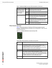
The SW3 switch on the FortiSwitch-5003A board is factory set by Fortinet with the
front panel 14/F8 interface enabled and the fabric backplane slot 14 disabled. This
means you can connect the FortiSwitch-5003A front panel 14/F8 interface to a
network but you cannot connect a FortiGate-5000 board in slot 14 to the fabric
backplane.
The SW3 switch on the FortiSwitch-5003A board can be used to switch between
enabling 14/F8 front panel interface and enabling the fabric backplane slot 14
interface.
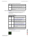
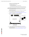
Figure 7: SW3 factory default setting (front panel interface 14/F8 enabled)
Figure 8: SW3 changed (backplane slot 14 enabled)
Default (Front panel 14/F8 interface enabled)
1 ON
2 OFF
3 ON
4 ON
1 2 3 4
ON
SW3
Backplane slot 14 enabled
1 OFF
2 OFF
3 ON
4 ON
1 2 3 4
ON
SW3


