FortiSwitch-5003A System Guide
6 01-30000-77803-20080917
Front panel LEDs and connectors FortiSwitch-5003A system
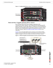
Figure 1: FortiSwitch-5003A front panel
• One front panel base backplane 10-gigabit optical or copper SFP+ interface
(BASE 10G) that connects to the base backplane channel
• Eight front panel fabric backplane 10-gigabit optical or copper SFP+ interfaces
(14/F8, F7, F6, F5, F4, F3, F2, and F1)
• One gigabit out of band management ethernet interface (MGMT)
• One RJ-45, RS-232 serial console connection (COM)
• Mounting hardware
• LED status indicators
• IEEE 802.1q VLANs
• IEEE 802.3ad layer-2 link aggregation
• Link aggregation using a hash algorithm based on source and destination IP
addresses
• Multi-Spanning Tree Protocol (MTSP) (IEEE 802.1s) to support redundant
FortiSwitch-5003A boards and external MTSP-compatible switches
• Heartbeat between FortiGate-5001A and FortiGate-5005FA2 boards and the
FortiSwitch-5003A over the fabric channel to support MTSP (configurable from
the FortiGate-5001A and FortiGate-5005FA2 systems)
• Standard FortiOS command line interface (CLI) for configuring fabric switch
settings (VLANs, MTSP, trunks, and so on)
Front panel LEDs and connectors
From the FortiSwitch-5003A font panel you can view the status of the board LEDs
to verify that the board is functioning normally. The front panel includes a reset
switch for restarting the FortiSwitch-5003A board.
The front panel also contains connectors to the fabric and base channels, an out
of band management ethernet interface, and an RJ-45 RS-232 console port for
connecting to the FortiSwitch-5003A CLI.
Base Network
Activity LEDs
Fabric Network
Activity LEDs
RJ-45 COM
Port
MGMT 1G
Copper
Interface
B1 B2
Base 1G
Copper
BASE 10G Optical
or Copper SFP
14/F8 F7 F6 F5 F4 F3 F2 F1
Fabric 10G Optical or Copper SFP
Extraction
Lever
Retention
Screw
Extraction
Lever
Retention
Screw
Hot Swap
LED
OOS
LED
Active
LED
Healthy
LED
Fault
LED
Reset
Switch


