


Hardware Specifications
September 2007 © 2007 Foundry Networks, Inc. 2 - 7
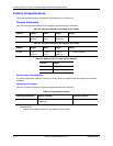
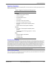
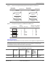
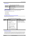
Figure 0.2 Console Port Pin Assignments Showing Cable Connection Options to a Terminal or PC
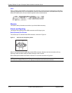
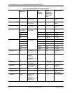
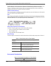
Figure 0.3 Pin assignment and signalling for 10/100BaseTX and 1000BaseT ports
Cable Specifications
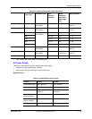
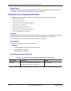
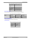
Table 0.12 lists the cable specifications for the cables used with the 10/100, Gigabit and 10-Gigabit Ethernet ports.
NOTE: Cable installation and network configuration will affect overall transmission capability. The numbers
provided below represent the accepted recommendations of the various standards. For network-specific
recommendations, consult your local Foundry reseller or system engineer.
Table 0.12: Cable length summary table
Cable Type
1
Connector Type Core
Diameter
(microns)
Modal
Bandwidth
(MHz*km) or
Wavelength
(nm)
Range (meters)
1000Base-BX-D Single-mode
Fiber (SMF)
LC connector for
SFP module
9 1490 nm 2 – 10000
(10km)
1
2
3
4
5
6
7
8
9
1
2
3
4
5
6
7
8
9
Reserved
DB-9 to DB-9
Female Switch
Reserved
Reserved
Reserved
Terminal or PC
1
2
3
4
5
6
7
8
9
8
3
2
20
7
6
4
5
22
Reserved
DB-9 to DB-25
Female Switch
Reserved
Reserved
Reserved
Terminal or PC
Pin Assignment Pin Number
1
2
3
4
5
6
7
8
Pin Number
1
2
3
4
5
6
7
8
8
1
1
8
MDI-X ports
RD+
RD-
TD+
Not used
TD-
Not used
Not used
Not used
100BaseTX and 1000BaseT
10BaseT
MDI-X ports
RD+
RD-
TD+
CMT
TD-
CMT
CMT
CMT