


Foundry NetIron M2404C/M2404F Metro Access Switches
January 2007 © 2007 Foundry Networks, Inc. 5
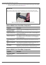
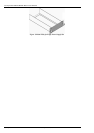
3. Gently insert the SFP tranceiver into the port until the module clicks into place. The module
is keyed to prevent incorrect insertion. See Figure 5.
Important Note
When inserting an SFP tranceiver into ports marked 27 or 28, verify that the SFP is facing
upside -down (as shown in figure below). All other SFP ports on the switch face right-side up.
Figure 5: Inserting an SFP, upside-down, into the Enhanced GigE Slot
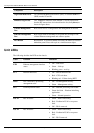
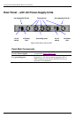
NetIron M2404C Front Panel Main Components
Component Description
For NetIron M2404C:
10/100baseTX Ports
24 RJ-45 sockets with 10/100 Mbps LAN speed auto sensing,
marked 1 to 24.
GigE Dual-Mode Ports
Two dual-mode1000baseX interface (SFP) or 10/100/1000BaseT
(RJ45) marked 25 and 26.
Enhanced GigE Ports
Two 1000baseX interface (SFP) marked 27 and 28. Please note
that the SFP transceivers are inserted into the slot, belly-down, as
shown in figure above.
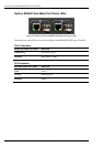
Console Management
Port
RJ45 socket for CLI configuration and management of the unit.
Ethernet Management
Port
RJ45 socket with 10/100 Mbps LAN speed auto sensing for out-
of-band Ethernet management and software update.
RST Button
Reset button. To avoid accidental activation, the button is recessed
behind the panel. Press with a pin or a similar narrow object.
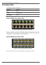
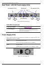
NetIron M2404F Front Panel Main Components
Component Description
For NetIron M2404F:
100baseX Ports
24 SFP sockets marked 1 to 24.