


Using the ASB520 MC68HC908QT2 Based Infrared Remote Control Reference PC Board DRM045
MOTOROLA Operational Description 11
Designer Reference Manual — DRM045
Section 2. Operational Description
2.1 Introduction
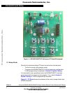
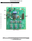
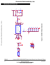
The following subsections describe the operation of the ASB520,
MC68HC908QT2 infrared remote control reference design system. LEDs,
switches, jumper blocks and FLASH programmer headers, and current monitor
jumper block are described here. Figure 2-1 shows the locations of these
items.
2.2 Push Buttons
There are six push button switches resident on the lower portion of the
reference PC board. They are labeled as switches SW1–SW6 on the PC board
schematic. Each button has a dedicated function. The switches are labeled as
POWER, PAUSE, PLAY, REVERSE, STOP, and FORWARD. These labels
describe the button’s operation function related to control of a DVD player.
2.3 LEDs
There are two LEDs located in the upper right hand corner of the PC board. The
LED labeled D1 is an infrared LED and the one labeled D2 is a visible red LED
and is used to show system activity.
2.3.1 Red Activity Indicator LED
D2 is a visible red LED and is used to show IR LED activity. It blinks as long
any push button is depressed
2.3.2 Infrared LED
D1 is an infrared LED. It is modulated to control the DVD.
Frees
cale Semiconductor,
I
Freescale Semiconductor, Inc.
For More Information On This Product,
Go to: www.freescale.com
nc...