


DRM045 Using the ASB520 MC68HC908QT2 Based Infrared Remote Control Reference PC Board
22 Design Considerations MOTOROLA
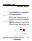
Design Considerations
A logic 1 from port A, bit 0 will turn the NPN transistor on, driving its collector
low. The low level applied to the base of the PNP transistor, Q2, will drive its
emitter to collector into conduction, illuminating the two LEDs. Resistor R5 is in
place to guarantee that Q1 is biased off during initial power on and before the
microcontroller’s program has configured port A, bit 1 to behave as a digital
output.
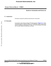
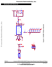
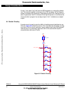
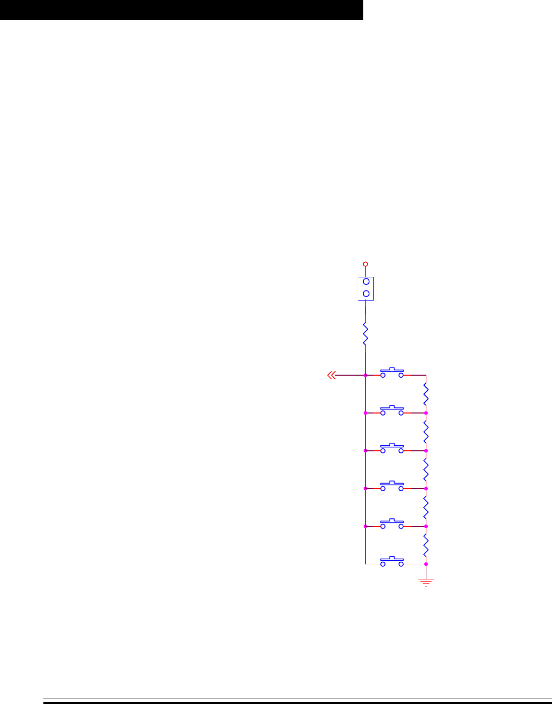
5.4 Switch Circuitry
A simple circuit is used to give the ability of reading several switches into an
A/D port. Figure 5-2 shows the circuit. This circuit has the advantage of using
only one I/O pin for the six switches. Using a switch matrix and the keyboard
interrupt pins is an alternative approach, but in this case would require a
microcontroller with more I/O pins.
Figure 5-2. Switch Circuitry
JP3
SW_DISC
1
1
2
2
Vdd
R11
4.7K
R12
2.2k
R15
1k
SW1
POWER
R14
470
R13
220
R9
3.3K
PTA1_ATD1
SW2
PLAY
SW3
FWD
SW6
REV
SW5
PAUSE
SW4
STOP
Frees
cale Semiconductor,
I
Freescale Semiconductor, Inc.
For More Information On This Product,
Go to: www.freescale.com
nc...