


Using the ASB520 MC68HC908QT2 Based Infrared Remote Control Reference PC Board DRM045
MOTOROLA Design Considerations 21
Designer Reference Manual — DRM045
Section 5. Design Considerations
5.1 Introduction
Microcontroller systems, in general, have a number of important design
considerations related to PC board layout and grounding considerations.
These design considerations are discussed in 5.2 Grounding, 5.3 Infrared
and Visible LED Drive Circuit, and 5.4 Switch Circuitry. A description of two
of the reference board’s major circuits are included in 5.3 Infrared and Visible
LED Drive Circuit and 5.4 Switch Circuitry.
5.2 Grounding
PC board layout is an important design consideration. In particular, ground
planes and how grounds are tied together influence noise immunity. To
maximize oscillator noise immunity, it is a good practice have ground plane
under the resonator, X1. One good grounding practice is to carry all of the
ground connections, in a star configuration, to a single point which could be the
power supply’s bulk capacitor or in this case, the battery ground terminal.
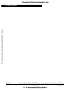
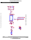
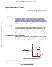
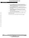
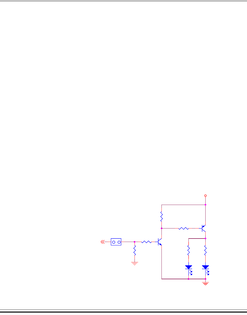
5.3 Infrared and Visible LED Drive Circuit
Figure 5-1 is the driver schematic, used to drive both LEDs on the PC board.
Because the microcontroller will not source or sink enough current to drive the
two LEDs, a discrete driver is necessary. This circuit uses two transistors. The
first transistor is a small signal NPN, followed by a small signal PNP transistor.
Figure 5-1. Infrared LED Drive Circuit
D2
RED
R4
1K
R3
47
R6
470
Vbat
R2
330
JP4
IR_DISC
1 2
12
R5
47K
To PTA0
Q2
2N3906
Q1
2N3904
D1
IR_LED
R1
47K
Frees
cale Semiconductor,
I
Freescale Semiconductor, Inc.
For More Information On This Product,
Go to: www.freescale.com
nc...