


5-4
Connec-
tor pin
number
11
12
13
14
15
16
17
18
19 to 30
31
Return
line pin
number
29
30
–
–
–
–
–
–
–
–
Direction
Output
Output
Output
Input
–
–
–
Output
–
Input
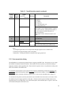
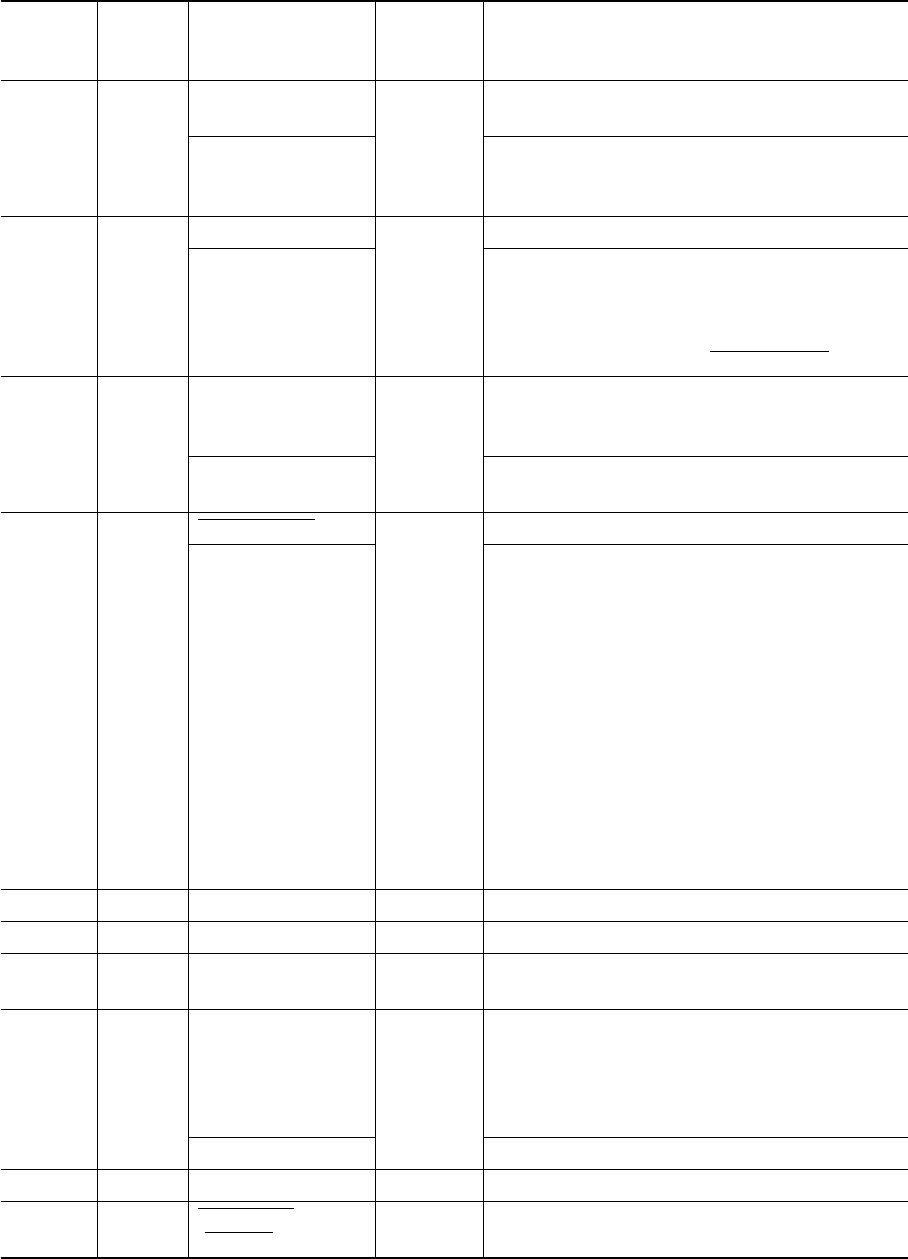
Description
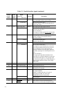
Data cannot be received when this signal is high,
e.g., if the buffer is full or an error occurs.
Reverse data transfer phase:
Data bit 3, data bit 7, then forward path (host to
printer) busy status
This signal goes high if paper runs out.
Reverse data transfer phase:
Data bit 2, then data bit 6
Reverse idle phase:
This signal is set high until the host requests data
and, after that, follows the Data Available signal.
This signal goes high when the printer is selected
(online), and goes low when the printer is
deselected (offline).
Reverse data transfer phase:
Data bit 1, then data bit 5
Not used
Reverse data transfer phase:
This signal is set low when the host can receive
data, and goes high when the host has received
data. Following a reverse data transfer, the
interface enters the reverse idle phase when the
Host Busy signal goes low and the printer has no
data.
Reverse idle phase:
This signal goes high when the Printer Clock
signal goes low so that the interface re-enters the
reverse data transfer phase. If it goes high with
the 1284 Active signal low, the 1284 idle phase is
aborted and the interface returns to the compat-
ibility mode.
No connection
Logic ground level (0 V)
Printer chassis ground line
FG and SG are connected.
+5 V source (up to 50 mA)
No output in default
Output is available when the +5V option is
selected for the <PIN-18> item by the
HARDWRE function in setup mode.
No connection
Twisted-pair return lines
If this signal is low for more than 50 µs, the
printer is reset to initial status and placed online.
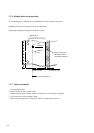
Table 5.1 Parallel interface signals (continued)
Signal
Compati mode
Nibble mode
Busy
Printer Busy
Paper Empty (PE)
Ack Data Req
Select (SLCT)
X Flag
Auto Feed XT
Host Busy
–
Signal Ground (SG)
Frame Ground (FG)
+5V
–
Signal Ground (SG)
Input Prime
(IN PRM)