


Product Facts ⏐ Issue: June 01, 2008 ⏐ Product: SPARC
®
Enterprise M5000 Page 27 / 38
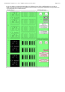
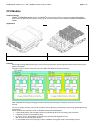
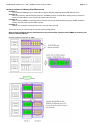
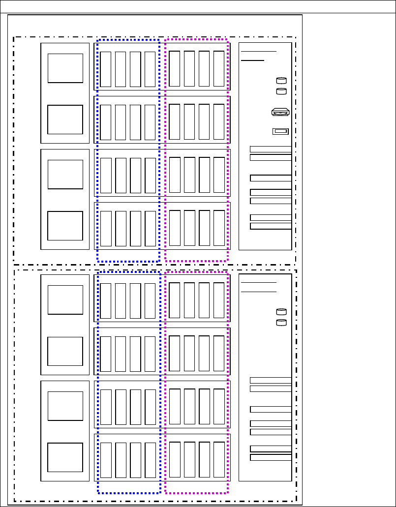
Mounting additional Memory with different sizes
MEM in SPARC
®
Enterprise M5000 is organized on each SB separately in two groups:
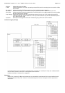
• Max. 16 DIMMs mounted in MEM#xA slots at SB#0 defined as Group A of SB#0.
• Max. 16 DIMMs mounted in MEM#xB slots at SB#0 defined as Group B of SB#0.
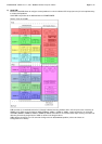
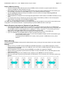
• In Group B at SB #0, all DIMMs must have the same Capacity. In Group A at SB #0, all DIMMs must have the same
Capacity and this Capacity must be equal or bigger than the DIMMs of Group B. This DIMM Mix within a SB is possible in
Uni-XSB and Quad-XSB Mode.
• Max. 16 DIMMs mounted in MEM#xA slots at SB#1 defined as Group A of SB#1.
• Max. 16 DIMMs mounted in MEM#xB slots at SB#1 defined as Group B of SB#1.
• In Group B at SB #1, all DIMMs must have the same Capacity. In Group A at SB #1, all DIMMs must have the same
Capacity and this Capacity must be equal or bigger than the DIMMs of Group B. This DIMM Mix within a SB is possible in
Uni-XSB and Quad-XSB Mode.
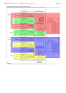
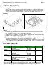
• Memory configurations and arrangements on SB#0 and on SB#1 can be different.
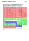
• On each used SB a minimum of one CPU Module and two Memory Boards are necessary. The optional second I/O-Board
also requires the minimum of CPU and Memory on SB#1.
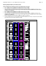
Logical diagram of memory locations
MEM#0A
MEM#1A
MEM#2A
MEM#3A
MEM#0B
MEM#1B
MEM#2B
MEM#3B
Memory Board #0
MEM#0AMEM#0A
MEM#1AMEM#1A
MEM#2AMEM#2A
MEM#3AMEM#3A
MEM#0BMEM#0B
MEM#1BMEM#1B
MEM#2BMEM#2B
MEM#3BMEM#3B
Memory Board #0
MEM#0A
MEM#1A
MEM#2A
MEM#3A
MEM#0B
MEM#1B
MEM#2B
MEM#3B
Memory Board #1
MEM#0AMEM#0A
MEM#1AMEM#1A
MEM#2AMEM#2A
MEM#3AMEM#3A
MEM#0BMEM#0B
MEM#1BMEM#1B
MEM#2BMEM#2B
MEM#3BMEM#3B
Memory Board #1
MEM#0A
MEM#1A
MEM#2A
MEM#3A
MEM#0B
MEM#1B
MEM#2B
MEM#3B
Memory Board #2
MEM#0AMEM#0A
MEM#1AMEM#1A
MEM#2AMEM#2A
MEM#3AMEM#3A
MEM#0BMEM#0B
MEM#1BMEM#1B
MEM#2BMEM#2B
MEM#3BMEM#3B
Memory Board #2
MEM#0A
MEM#1A
MEM#2A
MEM#3A
MEM#0B
MEM#1B
MEM#2B
MEM#3B
Memory Board #3
MEM#0AMEM#0A
MEM#1AMEM#1A
MEM#2AMEM#2A
MEM#3AMEM#3A
MEM#0BMEM#0B
MEM#1BMEM#1B
MEM#2BMEM#2B
MEM#3BMEM#3B
Memory Board #3
CPU Modul #0
CPU
Chip #0
CPU
Chip #1
CPU Modul #0
CPU
Chip #0
CPU
Chip #1
CPU Modul #1
CPU
Chip #2
CPU
Chip #3
CPU Modul #1
CPU
Chip #2
CPU
Chip #3
MEM#0A
MEM#1A
MEM#2A
MEM#3A
MEM#0B
MEM#1B
MEM#2B
MEM#3B
Memory Board #4
MEM#0AMEM#0A
MEM#1AMEM#1A
MEM#2AMEM#2A
MEM#3AMEM#3A
MEM#0BMEM#0B
MEM#1BMEM#1B
MEM#2BMEM#2B
MEM#3BMEM#3B
Memory Board #4
MEM#0A
MEM#1A
MEM#2A
MEM#3A
MEM#0B
MEM#1B
MEM#2B
MEM#3B
Memory Board #5
MEM#0AMEM#0A
MEM#1AMEM#1A
MEM#2AMEM#2A
MEM#3AMEM#3A
MEM#0BMEM#0B
MEM#1BMEM#1B
MEM#2BMEM#2B
MEM#3BMEM#3B
Memory Board #5
MEM#0A
MEM#1A
MEM#2A
MEM#3A
MEM#0B
MEM#1B
MEM#2B
MEM#3B
Memory Board #6
MEM#0AMEM#0A
MEM#1AMEM#1A
MEM#2AMEM#2A
MEM#3AMEM#3A
MEM#0BMEM#0B
MEM#1BMEM#1B
MEM#2BMEM#2B
MEM#3BMEM#3B
Memory Board #6
MEM#0A
MEM#1A
MEM#2A
MEM#3A
MEM#0B
MEM#1B
MEM#2B
MEM#3B
Memory Board #7
MEM#0AMEM#0A
MEM#1AMEM#1A
MEM#2AMEM#2A
MEM#3AMEM#3A
MEM#0BMEM#0B
MEM#1BMEM#1B
MEM#2BMEM#2B
MEM#3BMEM#3B
Memory Board #7
CPU Modul #2
CPU
Chip #4
CPU
Chip #5
CPU Modul #2
CPU
Chip #4
CPU
Chip #5
CPU Modul #3
CPU
Chip #6
CPU
Chip #7
CPU Modul #3
CPU
Chip #6
CPU
Chip #7
I/O-Board
(base)
HDD#0
HDD#1
DVD-ROM
Slots for:
DAT
Gigabit EthernetGigabit Ethernet
Gigabit EthernetGigabit Ethernet
PCI-XPCI-X
PCI-ExpressPCI-Express
PCI-ExpressPCI-Express
PCI-ExpressPCI-Express
PCI-ExpressPCI-Express
I/O-Board
(optional)
HDD#2
HDD#3
Slots for:
Gigabit EthernetGigabit Ethernet
Gigabit EthernetGigabit Ethernet
PCI-XPCI-X
PCI-ExpressPCI-Express
PCI-ExpressPCI-Express
PCI-ExpressPCI-Express
PCI-ExpressPCI-Express
SB#1
SB#0
Motherboard
Group A
Group B
Group A
Group B