


xiv C141-E064-03EN
FIGURES
page
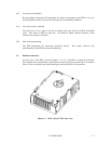
1.1 MAF series LC/MC outer view ...................................................................................... 1-5
1.2 MAF series LP/MP outer view....................................................................................... 1-6
1.3 MAE series LC outer view ............................................................................................. 1-6
1.4 MAE series LP outer view.............................................................................................. 1-7
1.5 MAG series LC/MC outer view...................................................................................... 1-7
1.6 MAG series LP/MP outer view ...................................................................................... 1-7
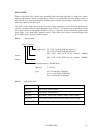
1.7 Disk/head configuration ................................................................................................. 1-8
1.8 System configuration...................................................................................................... 1-10
3.1 Cylinder configuration.................................................................................................... 3-2
3.2 Spare area in cylinders.................................................................................................... 3-5
3.3 Alternate cylinder ........................................................................................................... 3-5
3.4 Track format................................................................................................................... 3-6
3.5 Track skew/cylinder skew .............................................................................................. 3-7
3.6 Sector format .................................................................................................................. 3-8
3.7 Alternate block allocation by FORMAT UNIT command ............................................. 3-14
3.8 Alternate block allocation by REASSIGN BLOCKS command..................................... 3-15
4.1 External dimensions (MAF series LC/MC).................................................................... 4-2
4.2 External dimensions (MAF series LP/MP)..................................................................... 4-3
4.3 External dimensions (MAE series LC)........................................................................... 4-4
4.4 External dimensions (MAE series LP)............................................................................ 4-5
4.5 External dimensions (MAG series LC/MC) ................................................................... 4-6
4.6 External dimensions (MAG series LP/MP) .................................................................... 4-7
4.7 IDD directions ................................................................................................................ 4-8
4.8 Mounting frame structure............................................................................................... 4-9
4.9 Limitation of side-mounting........................................................................................... 4-9
4.10 Surface temperature measurement points (MAF series, MAE series, MAG series)........ 4-10
4.11 Service clearance area..................................................................................................... 4-11
4.12 Air pressure adjustment hole.......................................................................................... 4-12
4.13 Current waveform (+12 VDC)........................................................................................ 4-13
4.14 Power on/off sequence (1).............................................................................................. 4-14
4.15 Power on/off sequence (2).............................................................................................. 4-14
4.16 Power on/off sequence (3).............................................................................................. 4-14