


C141-E064-03EN4 - 28
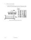
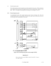
b. –WTP: Input signal (CN2-9, 10 pin)
By connecting the CN2-10 pins to the GND, writing operations into the IDD disc media
are set to disable.
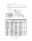
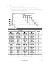
4.3.3 Cable connector requirements
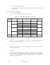
Table 4.2 lists the recommended components cable connection.
Table 4.2 Recommended components for connection
Applicable
model
Name Par number Manufacturer
Reference
(Figures 4.25
and 4.30)
LP/MP SCSI cable (CN1) Cable socket
(closed-end type)
786090-7 AMP S1
Signal cable — —
Power supply cable
(CN1)
Cable socket
housing
1-480424-0 AMP S2
Contact 60619-4
Cable 60617-4
External operator
panel (CN1)
Cable socket
housing
FCN-723J012/2M Fujitsu Limited S3
Contact FCN-723J-G/AM Fujitsu Limited
Cable AWG26 to 34
External operator
panel (CN2)
Cable socket
housing
FCN-723J016/2M Fujitsu Limited S4
Contact FCN-723J-G/AM Fujitsu Limited
Cable AWG28
LC/MC SCSI connector
(CN1)
Connector 787311-1 AMP
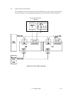
(1) SCSI cable
See Section 1.3, “Physical Requirements”, and Section 1.4, “Electrical Requirements”, in
SCSI Physical Interface Specifications.
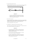
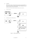
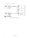
(2) Power cable
IDDs must be star-connected to the DC power supply (one to one connection) to reduce the
influence of load variations.
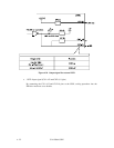
(3) DC ground
The DC ground cable must always be connected to the IDD because no fasten terminal
dedicated to SG is provided with the IDD. Therefore, when SG and FG are connected in the
system, it is necessary to connect SG and FG at the power supply or to connect SG of the
power supply to FG of the system.