


C141-E064-03EN4 - 8
4.1.2 Mounting
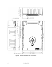
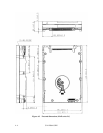
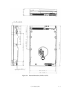
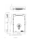
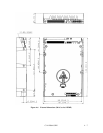
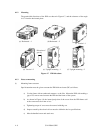
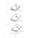
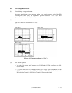
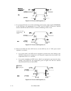
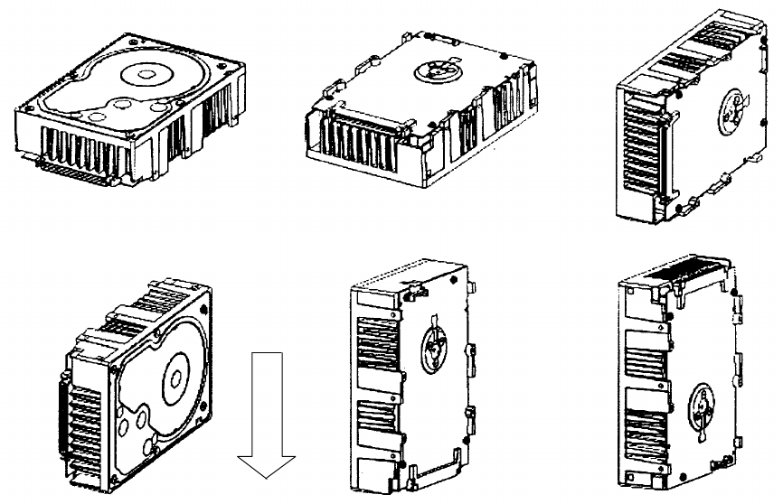
The permissible directions of the IDD are shown in Figure 4.7, and the tolerance of the angle
is ±5° from the horizontal plane.
Figure 4.7 IDD directions
4.1.3 Notes on mounting
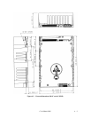
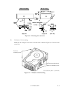
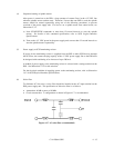
(1) Mounting frame structure
Special attention must be given to mount the IDD disk enclosure (DE) as follows.
a) Use the frame with an embossed structure, or the like. Mount the IDD with making a
gap of 2.5 mm or more between the IDD and the frame of the system.
b) As shown in Figure 4.8, the inward projection of the screw from the IDD frame wall
at the corner must be 4 mm or less.
c) Tightening torque of screw must be secured with 6kg-cm.
d) Impact caused by the electric driver must be within the device specifications.
e) Must be handled on an anti-static mat.
Direction of
gravity
(a) Horizontal –1 (b) Horizontal –2
(c) Vertical –1
(d) Vertical –2 (e) Upright mounting –1 (f) Upright mounting –2