


C141-E064-03EN 4 - 21
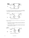
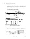
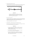
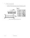
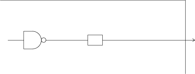
b. –Fault LED: Output signal (CN1-A2 pin)
The IDD indicates that the write-protect status is in effect (CN1-A12 is connected to the GND,
or the CN2-9 and CN2-10 are short-circuited.) A signal for driving the LED is output.
74LS06 or equivalent
150 Ω
NC1-A2
(IDD)
IMPORTANT
This signal is temporarily driven at the GND level when the micro
program reads the SCSI ID immediately after the power supply to
the IDD has been switched on (it is possible to set up the SCSI ID
by short circuiting CN1-A1 and CN1-A2.)
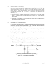
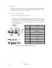
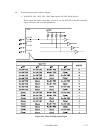
c. CN1-A4, CN1-A6 (reserved)
These pins are temporarily driven at the GND level when the micro program reads the SCSI ID
immediately after the power supply to the IDD has been switched on (it is possible to set up the
SCSI ID by short circuiting CN1-A3 and CN1-A4, and CN1-A5 and CN1-A6.)
These pins get high impedance status except above.
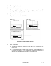
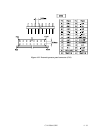
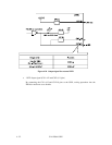
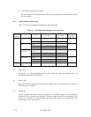
d. –LED and LED (V): Output signals (CN1-A8 pin and CN2-21, 22 pin)
These signals actuate the external LED as same as LED on the front panel of the disk
drive. The electrical requirements are given in Figure 4.24.
IMPORTANT
1. The external LED is identical in indication to the LED on the front of
the IDD. The meaning of indication can be selected with the
CHANGE DEFINITION command. For details of command, refer to
SCSI Logical Interface Specifications.
2. Any load other than the external LED (see Subsection 4.3.5) should
not be connected to the LED (V) and –LED terminals.
3. This signal is temporarily driven at the GND level when the micro
program reads the SCSI ID immediately after the power supply to the
IDD has been switched on (it is possible to set up the SCSI ID by
short circuiting CN1-A7 and CN1-A8.)