


Installation
5-4 C141-E235
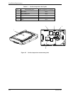
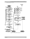
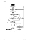
5.3 Mounting Drives
5.3.1 Mounting procedures
Since mounting the drive depends on the system cabinet structure, determine the work procedures
considering the requirements specific to each system. The general mounting method and items to be
checked are shown below.
See Subsection 4.1 for the details of requirements for installing the HDD.
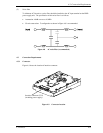
1) With a system to which an external operator panel is mounted, if it is difficult to access the
connector after the drive is mounted on the system cabinet, connect the external operator panel
cable before mounting the drive.
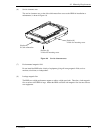
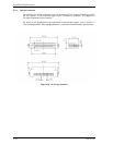
2) Fix the drive in the system cabinet with four mounting screws as follows:
• The drive has 10 mounting holes (both sides: 3 × 2, bottom: 4). Fix the drive by using four
mounting holes of both sides of the drive or the bottom. (See Figure 4.4)
• Use mounting screws of which lengths inside the drive mounting frame are 5.0 mm or less
when the screws are tightened (see Figure 4.3).
• When mounting the drive, be careful not to damage parts on the PCA.
3) Confirm the DE is not touching the frame on the system side excluding the screw installing part
after tightening the screws. At least 2.5mm of clearance is required between the DE and the
frame. (Indicated in Figure 4.3)
4) When using an electric screwdriver, use an electric screwdriver that does not apply a force on the
drive that would exceed the drive’s specifications.