Data Buffer Management
128 C141-C013
Segment 7
Segment 6
Segment 5
Segment 4
←
Read
←
Read
Write
→
Segment 3
Segment 2
Segment 1
Segment 0
Valid Data
Write
→
Disk Media
INIT
Segment
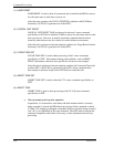
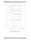
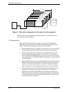
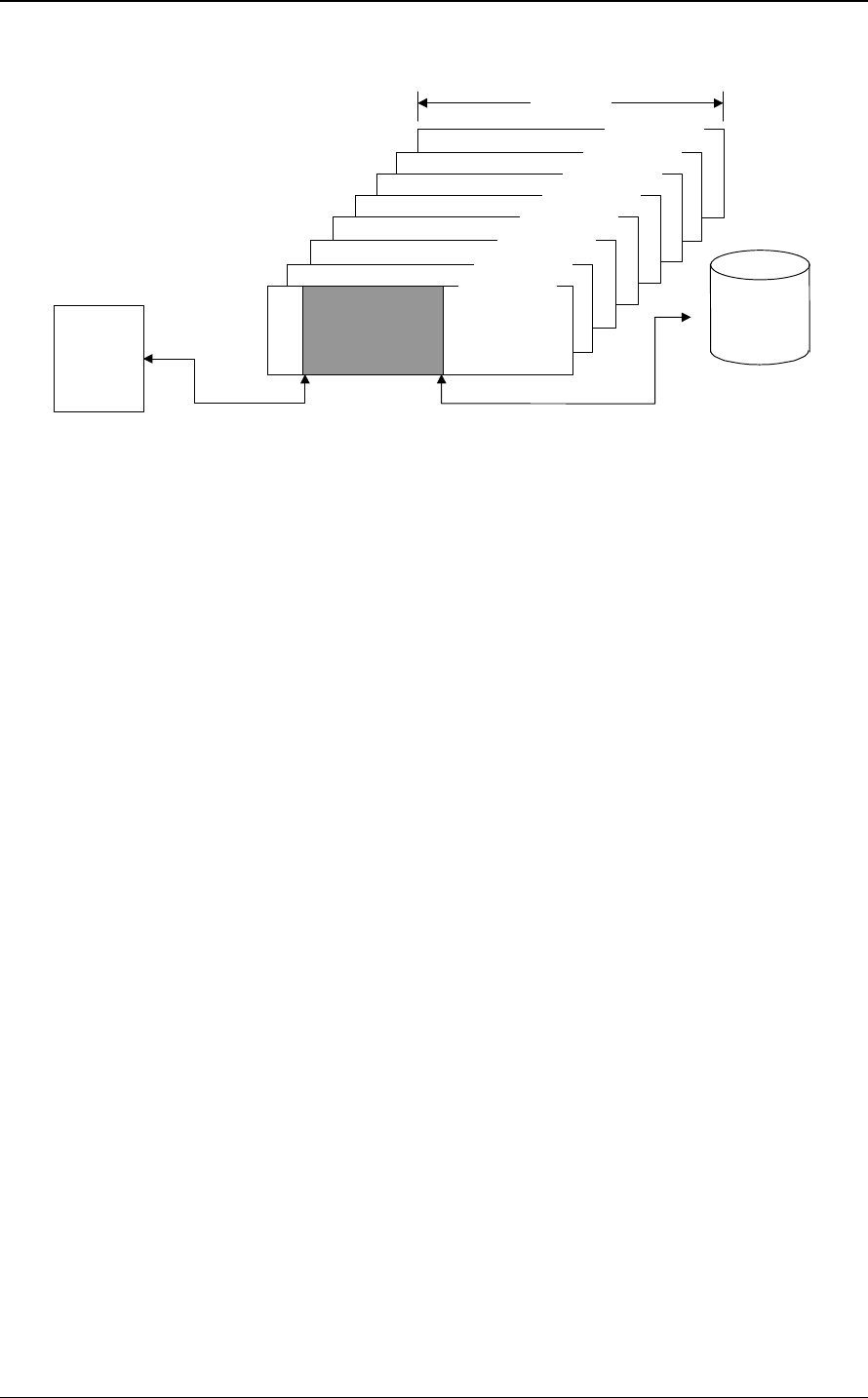
Figure 3.1 Data buffer configuration (in the case of 8 cache segments)
The basic functions and operations of the data buffer in a read operation and a
write operation are shown below.
(1) Read operation
Data read from the disk media are temporarily stored in the data buffer.
Then, they are transferred to the interface with the timing specified by the
HDD. The basic read operation procedure is as shown below.
1) When the HDD receives a command, it temporarily closes the connection
and locates the data block specified by the command on the medium.
2) When the target data block has been located, the HDD reads the data
form the disk media to the data buffer. At this time, if a recoverable
error is detected, the HDD performs error recovery processing according
to the specification in the MODE SELECT parameter or corrects the data
in the data buffer.
3) When the HDD has read out to the data buffer the amount of data that the
HDD itself has specified, it performs reconnection processing with the
interface and begins transferring data to the INIT from the data buffer
while continuing to read subsequent data blocks out to the data buffer.
4) If the data transfer rate of the INIT is high and the data buffer becomes
empty before completing the transfer of the number of data blocks
specified by the command, the HDD closes the interface at this point.
Thereafter, opening, data transfer, and closing operations (the operations
in 3) and 4) above) are repeated until all the data blocks specified in the
command have been transferred.


