


vii
SYSTEM CONFIGURATION
Analog
(Max. 16 ch)
Digital (Max. 64 ch)
Max. 6 ch
Max. 2 ch
Serial (Max. 8)
Remote Alarm
Panel (RAP)
VR-3016
GPS
Speed log
Heading
Echosounder
Autopilot
Engine telegraph
Steering gear
M/E remote system
Main air compressor
Bow thruster
Shell door system
Watertight doors
Fire doors
Anemometer
Fire detection
Main alarms
Others
Data Collecting
Unit (DCU)
VR-3010
Radar I/F
RI-3010*
100-230 VAC
24 VDC
: Standard supply equipment and cable
: Optional supply equipment and cable
: Local supply equipment and cable
VHF Audio
No. 1
Radar
VHF I/F
IF-5200
Bridge MIC
VR-5011
IEC 61162
serial data
Alarm Monitoring
System
Max.
2 ch
Live Player V4
VR-3020
Junction Box (JB)
IF-8530*
Junction Box (JB)
IF-8530 (max. 2)
24 VDC
Serial
(1ch)
Serial (Max. 8 ch)
Analog
(Max. 16 ch)
Digital (Max. 64 ch)
Data Recording Unit (DRU)
VR-5020-6G/VR-5020-9G
Waterproof MIC
VR-3012W
* Optional with VR-3000S
Serial (1 ch)
PC
No. 2
Radar
Radar Video
SW Interface
IF-1000RVC
Environmental category
DCU Protected from weather
DRU Exposed to weather
RAP Protected from weather
Bridge MIC Protected from weather
Waterproof MIC Exposed to weather
VHF I/F unit Protected from weather
JB Protected from weather
Radar Video SW Interface Protected from weather
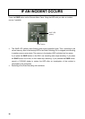
For the S-VDR, where it is impossible to obtain radar data, the AIS target data should be recorded
as a source of information from other ships. (Ref. IMO Res.MSC.163(78), section 5.4.7.)