


Installation
Apollo SL40 Installation Manual
5
SECTION 2 - INSTALLATION
This section describes the installation of the Apollo SL40 including mounting, wiring, and
connections. A post installation check-out procedure is included at the end of this section.
PRE-INSTALLATION INFORMATION
Always follow good avionics installation practices per FAA Advisory Circulars (AC) 43.13-
1A, 43.13-2A, and AC 20-67B, or later FAA approved revisions of these documents.
Follow the installation procedure in this section as it is presented for a successful installation.
Read the entire section before beginning the procedure. Perform the post installation check-
out before closing the work area in case problems occur.
INSTALLATION OVERVIEW
A successful installation should start with careful planning including determination of
mounting location for the SL40, antenna mounting, connections to microphones, speakers,
and headphones, cable routing, and other required modifications. Once the mounting location
has been determined, prepare the mounting frame for installation. It may be easier to complete
the wiring harness and attach the connectors to the mounting frame before installing the
mounting frame.
INSTALLATION CONSIDERATIONS
MOUNTING CONSIDERATIONS
The SL40 is designed to mount in the avionics stack in the aircraft instrument panel within
easy view and reach of the pilot. The standard package includes a mounting frame for ease of
mounting, connections, and service of the unit. Allow an additional one inch clearance to the
rear of the mounting frame for connectors and cables.
For typical installations, the SL40 does not require external cooling. When mounting the
SL40, leave a clearance of 1/8 to 1/4 inch between avionics to allow for circulation.
MINIMUM SYSTEM CONFIGURATION
The SL40 requires connections to the following equipment as a minimum:
x power input
x speaker or headphone output
x microphone input
x an antenna
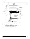
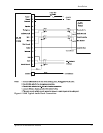
EQUIPMENT MOUNTING
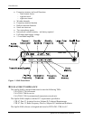
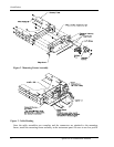
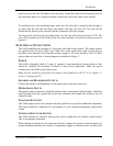
Once the cable assemblies have been made, attach the 15 pin dsub and coaxial cable
connectors to the rear connector mounting plate and the mounting frame as illustrated in
Figure 2 and Figure 3. Route the wiring bundle as appropriate. The rear connector plate should
be attached to the mounting frame before installing the frame in the instrument panel. The rear
connector plate can be used to tie down the cable assemblies. Connect the shield grounds
directly to the connector mounting plate.