Installation
Apollo SL40 Installation Manual
7
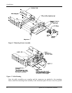
head screws so the unit will slide in and out freely. Attach the front of the mounting frame to
the instrument panel. Use support brackets to attach the rear of the frame to the aircraft.
To install the unit in the mounting frame, make sure the cam lock is rotated so the rear part is
up, then slide the unit into the frame and tighten with the 3/32 hex tool. The unit will be
pulled into the frame by the cam lock and the connectors will fully engage.
To remove the unit from the mounting frame, use the hex tool and turn the tool CCW. The
unit will be pushed out of the frame by the cam lock assembly. No special extraction tools are
required.
ELECTRICAL CONNECTIONS
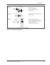
The SL40 installation kit includes a 15 pin dsub shell and crimp contacts. The crimp contacts
are specified for 20 to 24 AWG wire. Make the crimp connections with a crimp tool as
specified in the Special Tools Required section on page 4. All wires should be 20 to 24 AWG
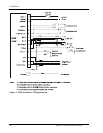
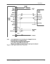
unless otherwise specified. A wiring diagram is included as Figure 5.
POWER
The SL40 is internally fused at 7 amps. A separate 5 amp (maximum) circuit breaker or fuse
should be installed for downline overload or short circuit protection. Make the power
connections to the SL40 using 20 awg wire.
Note: Circuits should be protected in accordance with guidelines in AC 43.13-1A, chapter 11,
section 2, paragraph 429.
SPEAKER AND HEADPHONE OUTPUTS
Connect the speaker and headphones to the output pins on the rear connector.
MICROPHONE INPUTS
Microphone input connections should be made using a twisted pair shielded cable. Attach the
signal ground to the mic ground pin on the rear connector and connect the shield to the rear
connector plate.
TRANSMIT KEY INPUT
The TxKey input on the rear connector must be pulled low to ground to enable the transmitter.
This input should be connected to a microphone or yoke mounted momentary push button
switch.
INTERCOM SELECTOR SWITCH
The SL40 includes an intercom function that can be enabled by an external control switch.
This is an optional connection.
When making connection for the intercom selection, connect the intercom selection input to a
remote mounted normally open switch. A momentary toggle or alternate action switch can be


