


Installation
12 Apollo SL40 Installation Manual
POST INSTALLATION CHECKOUT
Once the unit is installed, complete the checkout procedure to verify proper operation. Refer
to the User’s Guide for operating instructions.
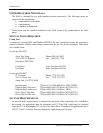
Mounting / Wiring Check
Verify that all cables are properly secured and shields are connected to the rear of the
mounting frame. Check the movement of the aircraft controls to verify that there is no
interference.
Receiver / Transmitter Operation
Tune the unit to a local frequency and verify the receiver output produces a clear and
understandable audio output. Verify the transmitter by contacting another station and getting a
report of reliable communications.
Antenna Check
The antenna VSWR can be checked using an inline watt meter in the antenna coax using
frequencies near both ends of the band. The VSWR should be < 2:1, and is not to exceed 3:1.
A VSWR of 2:1 will cause a drop in output power of approximately 12%, and 3:1 causes
approximately a 26% drop.
Interference Check
Check the SL40 while operating the other avionics and electrical systems on the aircraft to
verify that no significant interference exists, and that the SL40 does not cause significant
interference with other systems. Performance should be checked using low, high, and mid
band frequencies. Repeat during the flight test for equipment that is not checked on the
ground.
Sidetone Level Adjustment
The sidetone volume was preset at the factory to what should be an acceptable level. The level
can be adjusted in the System Functions mode. To adjust the sidetone level:
1. Press and hold the MON button for about two seconds. This will access the System
Functions mode.
2. Rotate the LARGE knob to display the SIDETONE LVL page.
3. Rotate the SMALL knob to change the level number. The range of the number is 000 to
255, with 128 producing one half of full rated output. A setting of 000 slaves the level to
the Volume knob.
4. Press any key to exit the Setup Functions mode.
5. Select an appropriate frequency, key the transmitter, and talk into the microphone to check
the level.
Receiver Squelch Adjustment
Adjustments to the receiver squelch level may be performed by using the RCVR SQELCH page
in the Test Mode. Values may be adjusted between 25 and 100.
1. Press and hold the and RCL keys while switching the unit on.
2. Turn the LARGE knob to the RCVR SQELCH page.
3. Press the key to start selection (the number will flash).
4. Turn the SMALL knob to change the value. Press MEM to store the value.