


Introduction
Apollo SL40 Installation Manual
3
The Apollo SL40 meets the additional standards as detailed in the Declaration of Conformity
included on page 31.
Note: Unauthorized changes or modifications to the SL40 may void the compliance to
required regulatory agencies and authorization for continued equipment usage.
UNPACKING THE EQUIPMENT
Carefully unpack the equipment. Visually inspect the package contents for any evidence of
shipping damage. Retain all shipping containers and packaging material in case reshipment is
necessary.
PACKAGE CONTENTS
As shipped from the Garmin AT, Inc. factory, the Apollo SL40 package includes most
necessary items for installation other than supplies normally available at the installation shop,
such as wire and cable ties, and required input and output equipment. The items included in
the package are listed in Table 1.
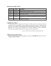
Table 1 Package Contents
Part # Description Qty
Comm unit
430-6040-2xx Apollo SL40 Comm Transceiver 1
Apollo SL40 Installation Kit, Part # 424-2006-2xx
162-0100 or
162-1575
15 pin dsub connector shell 1
162-1008 Right angle coax plug 1
202-0001 Cable tie 2
204-2100 Shoulder bushing 2
221-0400 4-40 x 1/4 SS pan head Phillips machine screw with lock washer 4
224-0404 4-40 x 1/4 SS flat head Phillips machine screw 6
245-0022 or
245-0027
Crimp contact for dsub, 20 to 24 awg wire 15
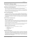
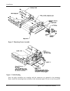
310-5181-01 Mounting frame 1
310-5187-01 Connector mounting plate 1
998-0048 3/32 hex driver 1
204-0037 Edge grommet 6”
Apollo SL40 Manual Kit, Part # 564-0064-2xx
560-0954-xx SL40 User’s manual 1
560-0956-xx SL40 Installation manual 1