


Magnum 1000 Workgroup Hubs Installation and User Guide (04/02)
26
www GarrettCom com
..
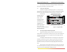
2. Wipe clean the ends of the dual connectors with a soft cloth or lint-free lens
tissue dampened in alcohol. Make certain the connectors are clean before connecting.
Note: One strand of the duplex fiber optic cable is coded using color bands
at regular intervals; you must use the color-coded strand on the
associated ports at each end of the fiber optic segment.
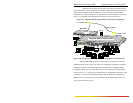
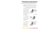
3. Connect the Transmit (TX) port (light colored post) on the Magnum PM-FST to
the Receive (RX) port of the remote device. Begin with the color-coded strand
of the cable for this first TX-to-RX connection.
4. Connect the Receive (RX) port (dark colored post) on the PM-FST to the
Transmit (TX) port of the remote device. Use the non-color coded fiber strand
for this.
5. The LINK LED on the front of the PM-FST will illuminate when a proper
connection has been established at both ends (and when power is ON in the
unit). If LINK is not lit after cable connection, the normal cause is improper
cable polarity. Swap the fiber cables at the Port Module connector to remedy
this situation.
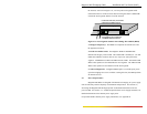
3.3.6 Connecting Fiber Optic (SMA-type, "Screw-on")*
The same five-step procedure as for fiber ST-type applies to FOIRL and
10BASE-FL applications using an RPM-SMA card used with SMA-type fiber
connectors. Follow the five steps as described in the Section 3.3.5 above.
When connecting fiber media to SMA connectors, do not over-tighten but
rather simply "finger tighten" these connections. Do not use a heavy tool (such as a
wrench) to tighten the fiber optic connectors as this might cause damage and result in
operating problems. Improper and excessive tightening may impair data transmission.
* The RPM-SMA is only available via special order.
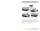
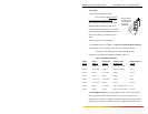
3.3.7 Connecting Single-Mode Fiber Optic (SMF)
When using the RPM-SMF, be sure to use single-mode fiber cable. Single-
mode fiber cable has a smaller diameter than multi-mode Fiber cable (2/15 - 8/60
microns for single-mode, 50/125 or 62.5/125 microns for multi-mode where xx/xx are
the diameters of the core and the core plus the cladding respectively). Because of this,
single-mode fiber allows full bandwidth at longer distances, and may be used to connect
nodes up to 10 Km apart. For operation with standard half-duplex Ethernet, collision
domain and / or power budget limitations may apply for distances over 5Km. Check
your single-mode configuration with an experienced network designer when you use
extended distances.
The same five-step procedure for multi-mode fiber ST-type applies to single-
mode fiber connectors. Follow the five steps listed in Section 3.3.5 above.