


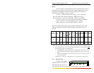

Magnum 1000 Workgroup Hubs Installation and User Guide (04/02)
37
www GarrettCom com
..
B3.0 APPLICATIONS
Magnum 1000 Workgroup Hubs are easily installed in a variety of
applications where -48VDC, 24VDC & 125VDC power is used as the primary power
source. The -48VDC, 24VDC & 125VDC power configuration provides an Ethernet
networking solution utilizing a special DC internal power supply in hubs having a
proven reliability record.
The solution is particularly useful in the telecommunication industry, where it
is common for facilities to operate on -48VDC power. Such companies include regular
and wireless telephone service providers, Internet Service Providers (ISPs), other
communication companies, and firms supplying network management and operations
monitoring equipment. In addition, many high-availability equipment services, such as
in broadcasters, publishers, heavy industrial plants, brokerage firms and others, often
use a battery backup system to maintain operations in the event of a power failure.
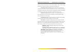
The 24VDC & 125VDC solution are particularly useful in the
Industrial environment, where it is common facilities to operate on 24VDC & 125VDC
power. The 125VDC solution is mainly used in Utilities Industries, such as Electric
substation, Electrical generating plant etc. Whereas 24VDC application is mainly in the
Industrial environment, such as chemical plants, paper mill, stone quarrying plant,
wastewater treatment Plant etc
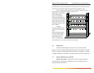
B4.0 INSTALLATION
This section describes the installation of the -48VDC, 24VDC &125VDC
power source leads to the -48VDC, 24VDC & 125VDC power terminal block on the
Magnum 1000’s. (see figure below).
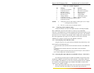
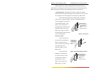
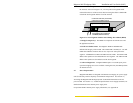
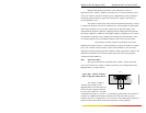
Figure B4.1: -48VDC Terminal
Block on Magnum 1000’s-48VDC
The -48VDC, 24VDC &
125VDC terminal block on the
Magnum 1000’s is located on the rear
of the unit and is equipped with three
(3) screw-down lead posts. The leads
are identified as negative (-), positive (+), and chassis ground (GND). The connection
procedure is straightforward. Simply connect the DC leads to the Switch’s power
terminals, positive (+) and negative (-) screws. The use of Ground (GND) is optional; it
connects to the Switch chassis. Ensure that each lead is securely tightened.
36-70VDC
_
+
GND