


Magnum 6K16-Series Managed Fiber Switch Installation and User Guide (04/06)
35
www GarrettCom com
..
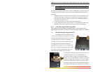
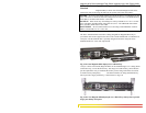
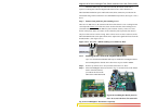
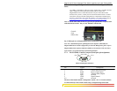
When the chassis top cover has been removed, the interior of the unit is
exposed. Looking down into the Magnum 6K16-Series unit, notice that there are
individual PM installation spaces and female latch (white) connectors provided on the
main board along with four stand-off’s for each 6KPM card position. (See Figure 3.6.1b)
above.
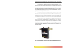
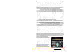
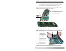
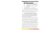
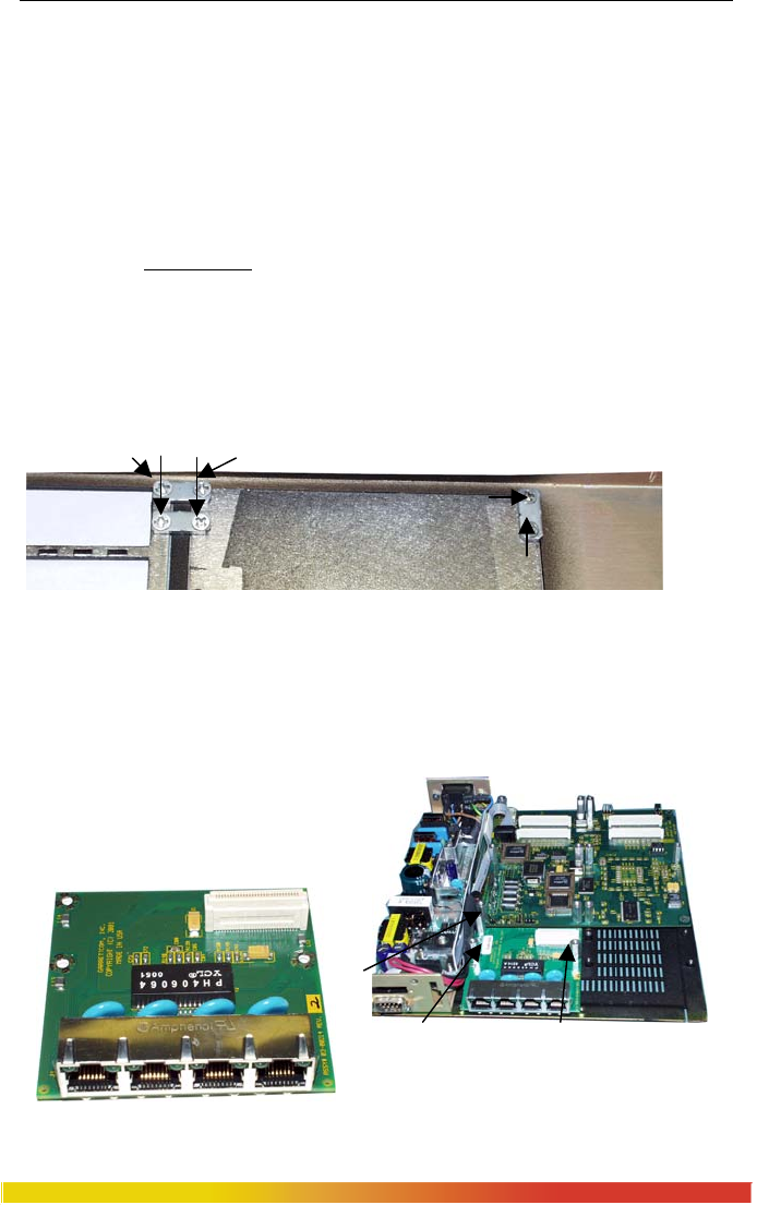
Step 3. Remove front panel face plate retaining screws
There are two PM slots (A, B) located on the front of the chassis cover. Looking into the
vertical placed Chassis cover
of the unit, there are three brackets with retaining screws
(#256 flat head ) which hold each PM Face plate card slot securely. These six screws
shown in the picture below are used to secure a PM face plate in position, but unscrew
only four of the screws as shown in Fig. below. These screws are also used to secure the
individual 6KPM cards screen plate which can be subjected to significant forces from the
attached cables. (See Figure 3.6.1c)
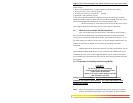
Figure 3.6.1c: Top View – 6KPM retaining screws hold Face Plate
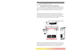
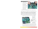
3.6.2 Installing 6KPM Cards in the Magnum 6K16-Series
Up to two front-mounted 6KPM cards may be installed in one Magnum 6K16-
Series Managed Fiber Switch unit. Follow these steps to install a 6KPM.
Step 1. Remove top chassis cover. See procedure in Section 3.6.1 above.
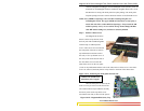
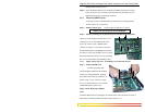
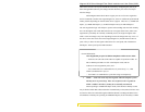
Step 2. Placed Granddaughter board (as shown in fig. 3.6.2a and 3.6.2b) on the chassis
built in stand off (female)
provided at the front of the
6K16-Series Main Board and
Fig 3.6.2b Granddaughter Board placed in
slot A & secured with three 5/16 stand-off’s
Fig 3.6.2a Granddaughter Board shown separately