


Magnum 6K16-Series Managed Fiber Switch Installation and User Guide (04/06)
43
www GarrettCom com
..
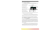
4.5 Flow-control, IEEE 802.3x standard
Magnum 6K16-Series Switches incorporate a flow-control mechanism for
Full-Duplex mode. The purpose of flow-control is to reduce the risk of data loss if a long
burst of activity causes the switch to save frames until its buffer memory is full. This is
most likely to occur when data is moving from a 100Mb port to a 10 Mb port and the
10Mb port is unable to keep up. It can also occur when multiple 100Mb ports are
attempting to transmit to one 100Mb port, and in other protracted heavy traffic situations.
Magnum 6K16-Series Switches implement the 802.3x flow control (non-
blocking) on Full-Duplex ports, which provides for a “PAUSE” packet to be transmitted
to the sender when the packet buffer is nearly filled and there is danger of lost packets.
The transmitting device is commanded to stop transmitting into the 6K16-Series Switch
port for sufficient time to let the Switch reduce the buffer space used. When the available
free-buffer queue increases, the Switch will send a “RESUME" packet to tell the
transmitter to start sending the packets. Of course, the transmitting device must also
support the 802.3x flow control standard in order to communicate properly during
normal operation.
Note
: When in Half-Duplex mode, the 6K16-Series Switch implements a
back-pressure algorithm on 10/100 Mb ports for flow control. That is, the switch prevents
frames from entering the device by forcing a collision indication on the half-duplex ports
that are receiving. This temporary “collision” delay allows the available buffer space to
improve as the switch catches up with the traffic flow.
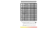
4.6 Power Budget Calculations for Magnum 6K16-Series PM’s with
Fiber Media
Receiver Sensitivity and Transmitter Power are the parameters necessary to
compute the power budget. To calculate the power budget of different fiber media
installations using Magnum products, the following equations should be used:
OPB (Optical Power Budget) = P
T
(min) - P
R
(min)
where P
T
= Transmitter Output Power, and P
R
= Receiver Sensitivity
Worst case OPB = OPB - 1dB(for LED aging) - 1dB(for insertion loss)
Worst case distance = {Worst case OPB, in dB} / [Cable Loss, in dB/Km]
where the “Cable Loss” for 62.5/125 and 50/125
m (M.m) is 2.8 dB/km,
and the “Cable Loss” for 100/140 (Multi-mode) is 3.3 dB/km,
and the “Cable Loss” for 9/125 (Single-mode) is 0.5 dB/km
and the “Cable Loss” for 9/125 (Single-mode) is 0.4 dB/km (LXSC25)
and the “Cable Loss” for 9/125 (Single-mode) is 0.25 dB/km
(LXSC40)
and the “Cable Loss” for 9/125 (Single-mode) is 0.2 dB/km (LXSC70)