


Stackable Personal Hubs Installation and User Guide (04/01)
15
www GarrettCom com
..
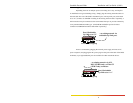
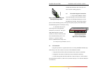
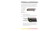
3.6 BNC Connection (Model ST80-B only)
Connect the ThinNet coax cable to the BNC connector on the rear of the ST80-B in
the same manner as is done for any standard BNC connection. The BNC port is specially
equipped with an internal termination switch that eliminates the need to use a "tee" connector
when the BNC cable is ending at the ST-80. When the switch is in the right position, the
connection is internally terminated. When switched to the left position, external termination
(“tee” connector, not supplied) is required. Some applications may require a "tee" connector,
used as a tap, to allow the 10BASE2 coax segment to continue on past the ST-80 port
connection.
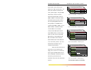
3.7 Fiber Optic Connection (Model ST80-F only)
The following procedure applies to FOIRL and 10BASE-FL multi-mode applications
using an ST80-F. (The primary difference between FOIRL and 10BASE-FL for users is the
maximum distance allowed. 10BASE-FL is used for a fiber segment length of up to 2000m,
while FOIRL is used for fiber segments of up to 1000m in length.)
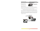
1. Before connecting the fiber optic cable, remove the protective dust caps from the
tips of the connectors on the ST80’s rear Fiber port. Save these dust caps for future use.
2. Wipe clean the ends of the dual connectors with a soft cloth or lint-free lens tissue
dampened in alcohol. Make certain the connectors are clean before connecting.
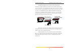
Note: One strand of the duplex fiber optic cable is coded using color bands at
regular intervals; you must use the color-coded strand on the associated ports at
each end of the fiber optic segment, i.e., TX on one end and RX on the other end.
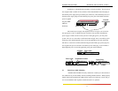
3. Connect the Transmit (TX) port (light colored post) of the ST80 to the Receive
(RX) port of the remote device. Use the color-coded strand of the cable for this first TX-to-
RX connection.
4. Connect the Receive (RX) port (dark colored post) of the ST80 to the Transmit
(TX) port of the remote device. Use the non-color coded fiber strand for this connection.
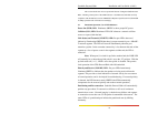
5. The LINK LED next to the rear fiber port will illuminate when a proper connection
has been established at both ends (and when power is ON in the unit). If LINK is not lit after
cable connection, the normal cause is improper cable polarity. Swap the fiber cables at the
ST80’s rear fiber port connectors to remedy this situation in most cases.