


Rear Panel 15
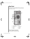
Voltage Selector Switch
Located on the back of the power supply module, this switch must be set to
the proper AC line voltage used in your locality (115VAC or 230VAC).
AC Power-In Connector
This is a connector into the power supply which provides the electrical
current to the system and its peripherals. Using the power cable supplied
with the system, connect the power supply into a grounded wall outlet.
Expansion Slot Cover Plates
These are cover plates over each of the expansion slots on the system board.
The system board has five PCI slots, one shared PCI/ISAslot, and one PCI/
RAIDport slot.
I/O Ports
The I/O ports on the rear panel provide the point of connection for the
peripherals that accompany the system and any others that you may
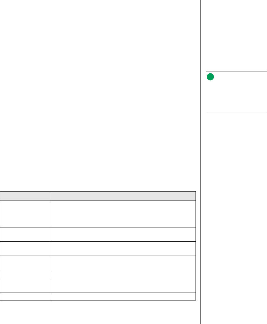
purchase. Table 3 defines the ports
Table 3: Rear Panel I/O Ports
Port Definition
Serial ports 1 and 2 These are high speed serial ports which use the First-In-First-Out
(FIFO) protocol. If you have a serial mouse, connect it to Serial
Port 1 (COM1). Other serial devices such as serial printers or
modems can also be connected these ports.
Parallel port Parallel devices such as parallel printers and scanners can be
connected to this port.
Mouse port This port supports any mouse with a miniature circular DIN (mini-
DIN) connector.
Keyboard port This port supports any keyboard with a miniature circular DIN
(mini-DIN) connector.
Video port Connects your monitor to the video interface card.
Dual USB ports These ports support any USB compliant devices. USB keyboards
and mice may not be compatible with power management.
Integrated LAN port This port supports an RJ45 connector to your LAN.
Note:
If your mouse has a mini-
DIN connector, you must
connect it to the Mouse
Port.
3435.boo Page 15 Thursday, August 6, 1998 7:12 AM