System Features 15
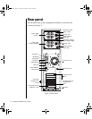
Power supplies
The system supports two 400-Watt redundant power supply modules
capable of load sharing. The standard configuration includes a single
module. The second module can be purchased as an option and provides
redundancy and hot-swap capabilities.
Power supply status lights
Each power supply module has a multi-color status light.
•
Green indicates normal operating mode
•
Amber indicates standby mode
•
No light indicates the power supply module is not receiving power
or has failed
Voltage selector switches
Located on the back of the power supply module, this switch must be set to
the proper AC line voltage used in your locality (115VAC or 230VAC). If
the optional second module is installed, there are two Voltage Selector
Switches.
AC power-in connectors
This is a connector into the power supply that provides the electrical current
to the system and its peripherals. Using the power cable supplied with the
system, connect the power supply into a wall outlet. If the optional second
module is installed, there are two AC Power-In connectors. If you use both
modules, plug each power cable into a separate wall outlet, preferably on
separate circuits.
Caution!
The voltage selector
switches are set at the
factory. Changing them
may result in severe
damage to the server.
4078tl.book Page 15 Tuesday, December 22, 1998 2:19 PM


