


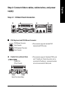

- 25 - Hardware Installation Process
English
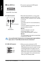
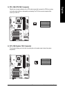
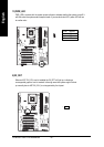
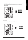
12) RAM_LED
Do not remove memory modules while DIMM LED is on. It might cause short or other
unexpected damages due to the 2.5V stand by voltage. Remove memory modules only when AC
Power cord is disconnected.
1
HD+
SPK-
19
HD-
SPK+
20
2
1
1
Speaker
Connector
Soft Power
Connector
1
1
1
MPD+
MPD-
Message LED/Power/
Sleep LED
PW-
PW+
IDE Hard Disk
Active LED
RSE+
RSE-
Reset Switch
NC
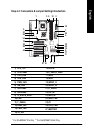
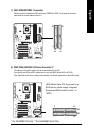
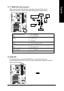
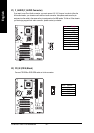
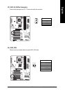
11) F_PANEL (2x10 pins connector)
Please connect the power LED, PC peaker, reset switch and power switch etc of your
chassis front panel to the F_PANEL connector according to the pin assignment above.
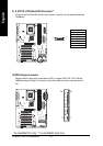
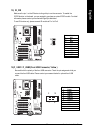
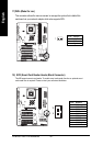
HD (IDE Hard Disk Active LED) Pin 1: LED anode(+)
(Blue) Pin 2: LED cathode(-)
SPK (Speaker Connector) Pin 1: VCC(+)
(Amber) Pin 2- Pin 3: NC
Pin 4: Data(-)
RES (Reset Switch) Open: Normal Operation
(Green) Close: Reset Hardware System
PW (Soft Power Connector) Open: Normal Operation
(Red) Close: Power On/Off
MSG(Message LED/Power/ Pin 1: LED anode(+)
Sleep LED)(Yellow) Pin 2: LED cathode(-)
NC( Purple) NC
+-