


GA-M59SLI-S5/GA-M59SLI-S4 Motherboard - 96 -
English
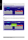
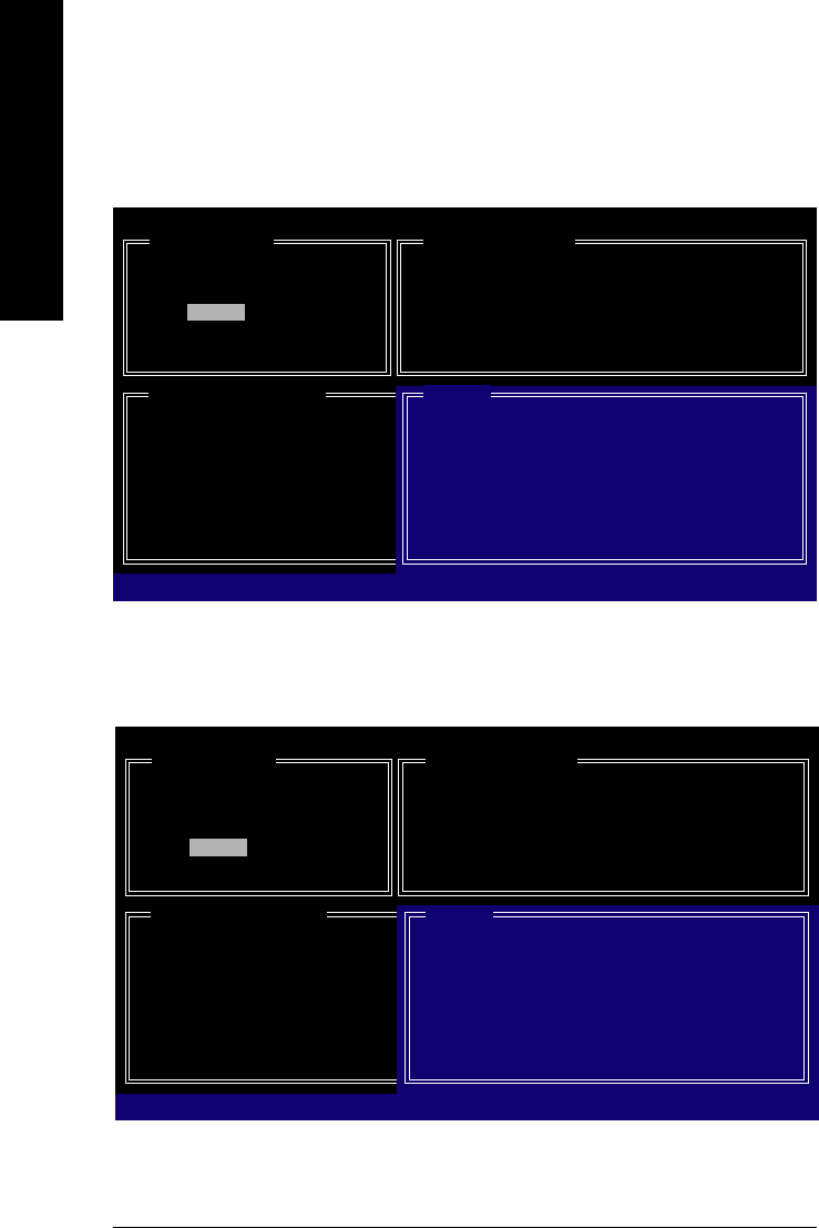
Figure 7
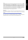
Figure 8
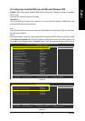
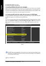
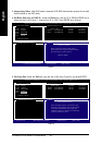
3. Assign Array Disks: After RAID mode is selected, RAID BIOS automatically assigns the two hard
disks installed as the RAID disks.
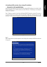
4. Set Block Size (only for RAID 0): Under the Block item, use the UP or DOWN ARROW key to
select the block size (Figure 7), ranging from 4K to 128K. Press ENTER when finished.
GIGA-BYTE Technology Corp. PCIE-to-SATAII/IDE RAID Controller BIOS V1.06.12
[ Create New RAID ]
Name: JRAID
Level: 0-Stripe
Disks: Select Disk
Block: 128KB
Size: 240GB
Confirm Creation
[ RAID Disk Drive List ]
[]-Switch RAID Block Size [ENTER]-Next [ESC]-Abort
[ Hard Disk Drive List ]
Mode Name Available Type/Status
HDD0: ST3120026AS 120 GB Non-RAID
HDD1: ST3120026AS 120 GB Non-RAID
[ Help ]
Setting Stripe Block
Select a stripe size which will be used to
divide data from/to seperate RAID members.
The following are typical values:
RAID 0-128KB
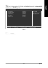
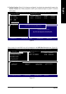
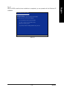
5. Set Array Size: Under the Size item, type the size of the array (Figure 8), and press ENTER.
GIGA-BYTE Technology Corp. PCIE-to-SATAII/IDE RAID Controller BIOS V1.06.12
[ Create New RAID ]
Name: JRAID
Level: 0-Stripe
Disks: Select Disk
Block: 128KB
Size: 240GB
Confirm Creation
[ RAID Disk Drive List ]
[]-Switch Unit [DEL,BS]-Delete Number [ENTER]-Next [ESC]-Abort
[ Hard Disk Drive List ]
Mode Name Available Type/Status
HDD0: ST3120026AS 120 GB Non-RAID
HDD1: ST3120026AS 120 GB Non-RAID
[ Help ]
Setting RAID Capacity
Enter the RAID capacity. The default value
indicates the maximum capacity determined
by the selected members. If less than the
maximum capacity is chosen, the remaining
capacity would be no used.