


RCV56HCF PCI/CardBus Modem Designer’s Guide
ROCKWELL PROPRIETARY INFORMATION
1129
3-20
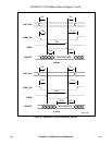
3.2.3 MDP
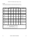
The MDP digital electrical characteristics for the hardware interface signals are listed in Table 3-9.
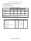
The MDP analog electrical characteristics for the hardware interface signals are listed in Table 3-10.
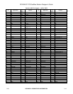
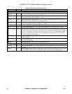
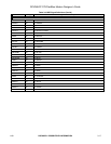
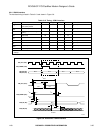
Table 3-9. MDP Digital Electrical Characteristics
Parameter Symbol Min. Typ. Max. Units
Test Conditions
1
Input High Voltage V
IH
VDC
Type IA 2.0 – VCC + 0.3
Type IE – 4.0 – Note 2.
Input High Current I
IH
µA V
IN
= 3.6 V, V
CC
= 3.6 V
Type IB – – 40
Input Low Voltage V
IL
VDC
Type IA –0.3 – 0.8
Type IE – 1.0 – Note 2.
Input Low Current I
IL
– – -40 µA
Input Leakage Current I
IN
±2.5 µADC V
IN
= 0 to 3.3V, V
CC
= 3.6 V
Output High Voltage V
OH
VDC
Type OA 2.4 – – I
LOAD
= – 100 µA
Type OB 2.4 – – I
LOAD
= 0 mA
Output Low Voltage V
OL
VDC
Type OA – – 0.4 I
LOAD
= 1.6 mA
Type OB – – 0.4 I
LOAD
= 0.8 mA
Three-State (Off) Current I
TSI
±10 µADC V
IN
= 0 V to VCC
Capacitive Load C
L
pF
Types IA and ID – 10
Type IB – 20
Capacitive Drive C
D
pF
Types OA and OB – 10
Circuit Type
Type IA TTL
Type IB TTL with pull-up
Type ID ~RES
Types OA and OB TTL with 3-state
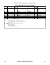
Notes:
1. Test Conditions: VCC = 3.3V ±0.3V, TA = 0°C to 70°C, (unless otherwise stated).
Output loads: Data bus (D0-D7), address bus (A0-A15), chip selects,
DRD#, and DWR# loads = 70 pF + one TTL load.
Other = 50 pF + one TTL load.
2. Type IE inputs are centered approximately 2.5 V and swing 1.5 V
PEAK
in each direction.
3. Type OE outputs provide oscillator feedback when operating with an external crystal.