


RCV56HCF PCI/CardBus Modem Designer’s Guide
1129
ROCKWELL PROPRIETARY INFORMATION
3-25
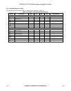
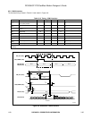
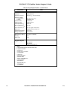
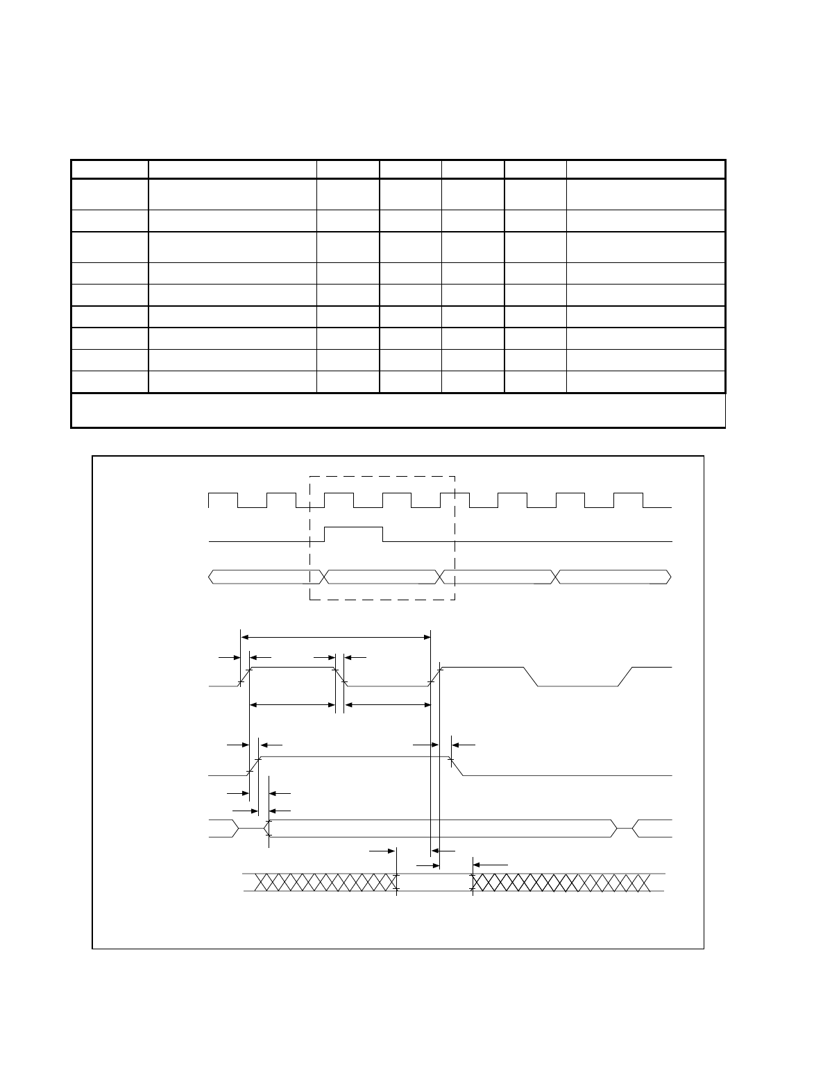
3.3.4 IOM-2 Interface
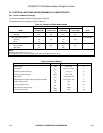
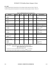
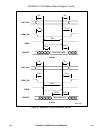
The interface timing is listed in Table 3-13 and shown in Figure 3-8.
Table 3-13. Timing - IOM-2 Interface
Symbol Parameter Min Typ. Max Units Test Condition
t
r,
t
f
Data clock (DCL) and frame
sync (FSC) rise/fall
––30nsC
L
= 25 pF
t
DCL
Data clock period (note 1) 565 651 735 ns C
L
= 25 pF
t
wH,
t
wL
Data clock pulse width high/low
(note 1)
200 310 420 ns
t
sD
Data setup 32 – – ns
t
hD
Data hold 32 – – ns
t
dF
Frame advance 0 65 130 ns C
L
= 25 pF
t
hF
Frame hold 20 – – ns C
L
= 25 pF
t
dDC
Data delay clock – 20 100 ns C
L
= 150 pF
t
dDF
Data delay frame – – 150 ns C
L
= 150 pF
Notes:
1. 768 bps.
Bit N Bit 0
Bit 0
Detail a
Detail a
t
wH
t
sD
t
dDF
t
dDC
t
dF
t
hD
t
wL
t
DCL
t
r
t
f
Bit 1 Bit 2
IOM_DU (DU)
IOM_DD (DD)
IOM_FRAME (FSC)
IOM_CLK (DCL)
IOM_DD (DD)
IOM_DU (DU)
IOM_FRAME (FSC)
IOM_CLK (DCL)
1123F3-9
t
hF
Figure 3-8. Waveforms - IOM-2 Interface