


1
2
3
4
5
6
7
1
2
3
4
5
6
7
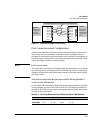
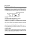
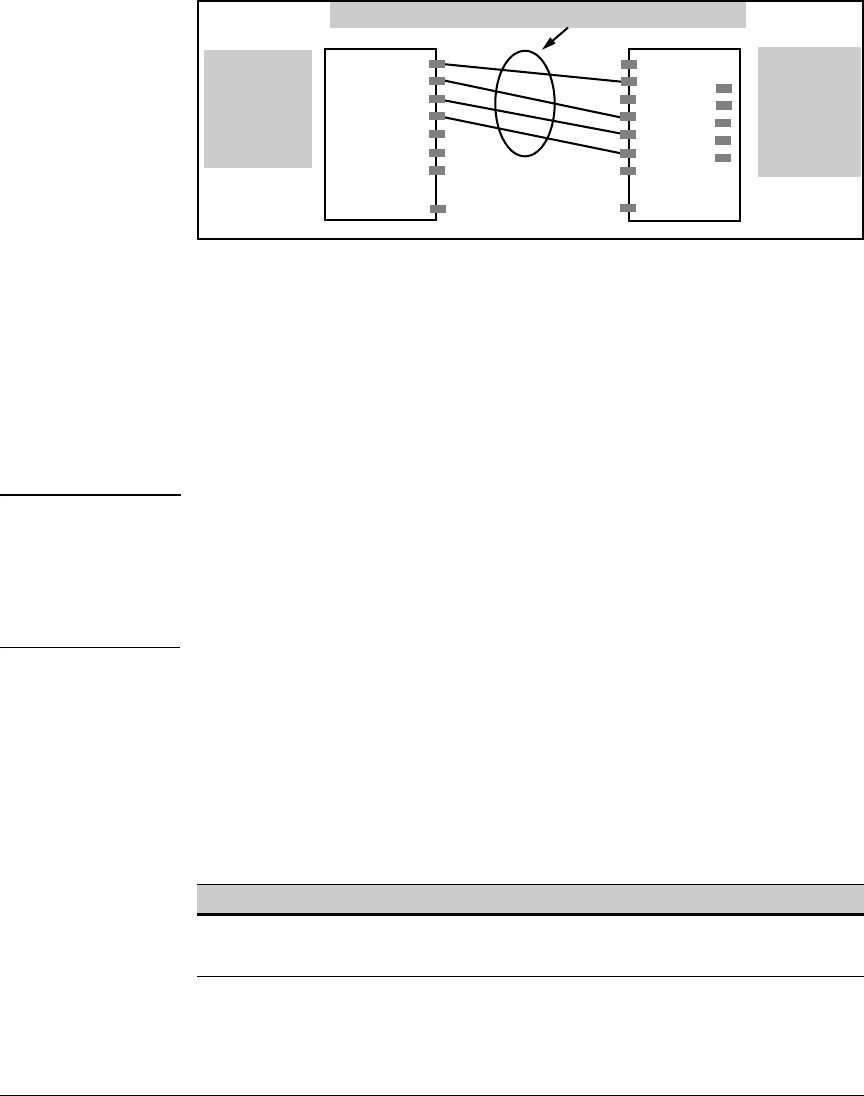
Port Trunking
Port Status and Configuration
Switch 1:
Ports c1 - c4
configured
as a port
trunk group.
The multiple physical links in a trunk behave as one logical link
port c
port c
port c
port c
port c
port c
port c
. . .
port n
port a
port a
port a
port a
port a
port a
port a
. . .
port n
Switch 2:
Ports a2 and
a4 - a6 are
configured as
a port trunk
group
Figure 12-1. Conceptual Example of Port Trunking
Port Connections and Configuration
All port trunk links must be point-to-point connections between the switch
and a router, server, workstation, or another switch configured for port
trunking. No intervening, non-trunking devices are allowed. It is important to
note that ports on both ends of a port trunk group must have the same mode
(speed and duplex) and flow control settings.
Note Link Connections
The switch does not support trunking through an intermediate, non-trunking
device such as a hub, or using more than one media type in a port trunk group.
Similarly, all links in the same trunk group must have the same speed, duplex,
and flow control.
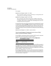
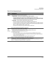
Trunk Group Boundary Requirement with IP Routing Enabled
on the Series 2800 Switch
On the Switch 2824 and Switch 2848, trunk groups can generally be specified
as any grouping of ports on the switch. However, if IP routing is enabled on
the switch, all of the ports in a given trunk group must be in the same group
of ports, as shown in table
2.
Table 10-2. Port Group Boundaries when IP Routing Enabled - 2800 Switches
Port Groups
Switch 2824 1 -12 13 - 24
n/a n/a
Switch 2848 1 -12 13 - 24 25-36 37 - 48
12-3