


Index-4 Maintenance and Service Guide
R
recycling
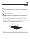
battery
10–1
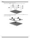
display components
10–1
removal/replacement
preliminaries
4–1
procedures
4–5
right-side components
2–9
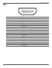
RJ-11 jack
connector pinout
8–5
location
2–9
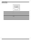
RJ-45 jack
connector pinout
8–4
location
2–8
RTC battery
illustrated
3–9
removal
4–26
spare part number
4–26
Rubber Feet Kit, spare part number
3–5, 3–12, 4–6
S
Screw Kit, spare part number 3–10, 3–12
screw listing
7–1
security cable slot
2–8
Security menu
5–3
security, product description
1–2
service considerations
4–1
solid-state module
precautions
4–2
product description
1–1
removal
4–20
spare part numbers
3–4, 3–8, 3–14, 4–20
speakers
location
2–3
spare part number
3–3, 3–13
specifications
computer
6–1
display assembly
6–2
DVD-ROM drive
6–3
optical drive
6–3
system DMA
6–4
system I/O address
6–7
system interrupt
6–6
system memory map
6–5
switch components
2–3
switch cover
removal
4–8
spare part number
3–3, 3–12, 4–8
system board
removal
4–41
spare part number
3–5, 3–14, 4–41
System Configuration menu
5–4
system DMA specifications
6–4
system I/O address specifications
6–7
system interrupt specifications
6–6
system memory map specifications
6–5
T
tools required 4–1
top components
2–1
top cover
removal
4–22
spare part number
3–3, 3–12, 4–22
TouchPad
2–6
TouchPad buttons
2–6
U
Universal Serial Bus (USB)
port
2–8, 2–9
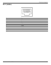
Universal Serial Bus (USB) port
connector pinout
8–6
USB board
illustrated
3–7
removal
4–27
spare part number
4–27
V
vent 2–8
W
warranty period 3–1, 4–5
Windows applications key
2–4
Windows logo key
2–4
wireless antenna
disconnecting
4–19
illustrated
3–6
locations
2–1
wireless button
2–7
wireless light
2–7
wireless, product description
1–2
WLAN module
removal
4–18
spare part numbers
3–4, 3–5, 3–11, 3–12, 4–18
WLAN module bracket, removal
4–19
workstation guidelines
4–4