


2-4
Installing the Access Point 530
Installation Procedures
Installing the
Access Point 530
1. Prepare the Installation Site
■ Cabling Infrastructure - Ensure that the cabling infrastructure meets
the necessary network specifications. See the following table for cable
types and lengths, and see appendix B, “Access Point Port and Network
Cables” for more information.
Table 2-1. Summary of Cable Types to Use With the Access Point
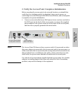
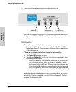
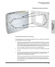
■ Installation Location - Before installing the access point, plan its loca-
tion and orientation relative to other devices and equipment:
• Try to place the access point in the center of your wireless network.
Normally, the higher you place the antennas, the better the perfor-
mance. You may need to reposition the access point after testing the
signal strength on several wireless stations to ensure that the access
point’s location provides optimal reception throughout the service
area.
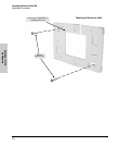
• At the back of the access point, leave at least 7.6 cm (3 inches) of
space for the twisted-pair cabling and the power cord.
• On the sides of the access point, leave at least 7.6 cm (3 inches) for
cooling.
Port Type Cable Type Length Limits
Twisted-Pair Cables
10/100Base-TX • 10 Mbps operation:
Category 3, 4, or 5, 100-ohm unshielded
twisted-pair (UTP)
• 100 Mbps operation:
Category 5, 100-ohm UTP cable.
100 meters
Note: Since the 10Base-T operation is through
the 10/100Base-TX port on the access point, if
you ever want to upgrade the ports on other
devices to 100Base-TX, it would be best to
cable the 10/100Base-TX port on the access
point initially with category 5 cable.
The 10/100-Base-TX port on the
Access Point 530 uses the “HP Auto MDIX”
feature, which means that you can use either
straight-through or crossover twisted-pair
cables to connect the access point to a switch
or workstation.