


2-13
Installing the Access Point 530
Installation Procedures
Installing the
Access Point 530
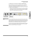
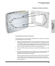
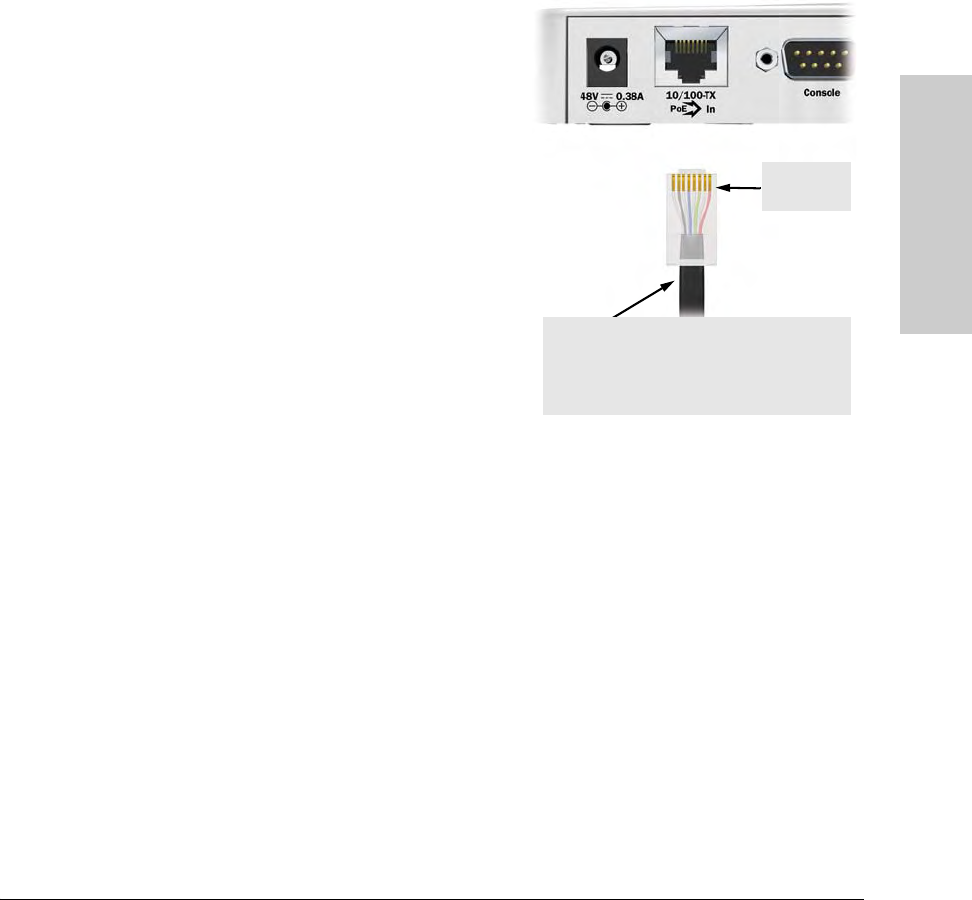
5. Connect the Network Cable
Connect the network cable, described under “Cabling Infrastructure”
(page 2-4), from the network device or your patch panel to the RJ-45 port on
the access point.
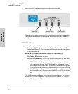
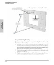
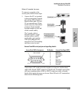
Using the RJ-45 Connectors
To connect:
Push the RJ-45 plug into the RJ-45
port until the tab on the plug clicks
into place. When power is on for the
access point and for the connected
device, the 10/100Base-TX link LED
should light to confirm a powered-on
device (for example, a switch) is at
the other end of the cable.
If the 10/100Base-TX link LED does
not go on when the network cable is
connected to the port, see “Restoring
Custom and Factory Default Config-
urations” in chapter 5, “Trouble-
shooting”.
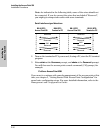
To disconnect:
Press the small tab on the plug and
pull the plug out of the port.
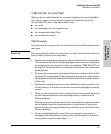
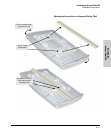
6. (Optional) Connect External Antennas to the Access
Point
If you intend to use optional external antennas with the access point, connect
them by following the instructions in chapter 4, “Using an External Antenna
with the Access Point 530”.
RJ-45
connector
Cable:
• Category 3, 4, or 5 for 10 Mbps ports (UTP)
• Category 5 or better for 100 Mbps ports (UTP)
Maximum distance: 100 meters