


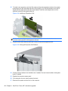
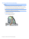
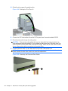
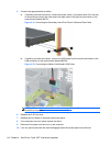
10. Rotate the drive cage to its upright position.
Figure 4-24 Rotating the Drive Cage Up
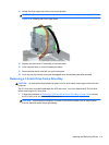
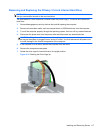
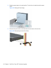
11. Connect the SATA data cable to the white SATA system board connector labeled SATA2.
12. Route the data cable through the cable guides.
CAUTION: There are two cable guides that keep the data cable from being pinched by the
drive cage when raising or lowering it. One is located on the bottom side of the drive cage. The
other is located on the chassis frame under the drive cage. Ensure that the data cable is routed
through these guides before connecting it to the optical drive.
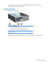
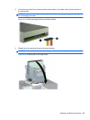
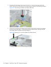
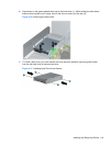
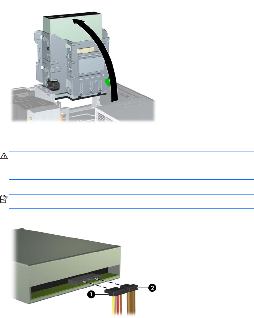
13. Connect the power cable (1) and data cable (2) to the rear of the optical drive.
NOTE: The power cable for the optical drive is a three-headed cable that is routed from the
system board to the hard drive, then to the rear of the optical drive.
Figure 4-25 Connecting the Power and Data Cables
112 Chapter 4 Small Form Factor (SFF) Hardware Upgrades