


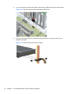
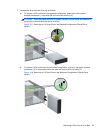
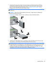
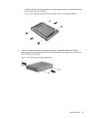
7. Install four M3 metric guide screws in the lower holes on each side of the drive (1). HP has
provided four extra M3 metric guide screws on the 5.25-inch drive bracket under the access
panel. The M3 metric guide screws are black. Refer to
Installing Drives on page 37 for an
illustration of the extra M3 metric guide screws location.
NOTE: When replacing the drive, transfer the four M3 metric guide screws from the old drive to
the new one.
CAUTION: Use only 5-mm long screws as guide screws. Longer screws can damage the
internal components of the drive.
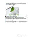
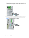
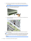
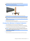
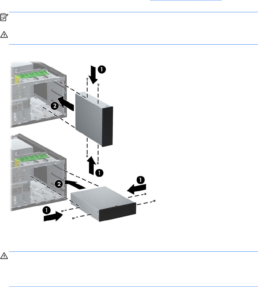
Figure 2-22 Installing a 5.25-Inch Drive in a Minitower (top) and Desktop (bottom)
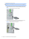
8. Install the drive in the desired drive bay by sliding it all the way into the front of the drive cage
until it locks (2). The drivelock automatically secures the drive in the bay.
CAUTION: The bottom 5.25-inch drive bay has a shorter depth than the upper two bays. The
bottom bay supports a half-height drive or other device that is no more than 14.5 cm (5.7 inches)
in depth. Do not try to force a larger drive, such as an optical drive, into the bottom bay. This
could cause damage to the drive and the system board. The use of unnecessary force when
installing any drive into the drive bay may result in damage to the drive.
Installing Drives 39