


Fan/heat sink assembly
NOTE: The fan/heat sink assembly includes replacement thermal material.
Description Spare part number
For use in AMD UMA computer models 640896-001
For use in Intel UMA computer models 641024-001
For use in Intel discrete computer models 641025-001
For use in AMD A60M UMA computer models 657143-001
For use in AMD A50M UMA computer models 657145-001
Before removing the fan/heat sink assembly, remove the following components:
1. Battery (see
Battery on page 41)
2. Service door (see
Service door on page 42)
3. Hard drive (see
Hard drive on page 43)
4. Optical drive (see
Optical drive on page 45)
5. WLAN module (see
WLAN module on page 47)
6. Memory module (see
Memory module on page 49)
7. Keyboard (see
Keyboard on page 51)
8. Top cover (see
Top cover on page 53)
9.
USB board (see
USB board on page 60)
10. Display assembly (see
Display assembly on page 63)
11. Power connector (see
Power connector on page 62)
12. System board (see
System board on page 69)
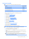
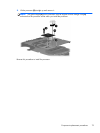
Remove the fan/heat assembly (fan/heat sink appearance may vary):
NOTE: Steps 1 through 5 apply only to computer models equipped with Intel processors.
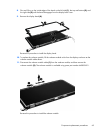
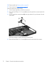
1. Turn the system board right-side up, with the front toward you.
2. Disconnect the fan cable from the system board (1).
3. Remove the Phillips 3.0 x 2.0 screw (2) that secures the fan/heat sink assembly to the system
board.
4. Follow the sequence embossed on heat sink to loosen the five Phillips 10.0 x 2.0 captive screws
(3) that secure the fan/heat sink assembly to the system board.
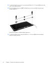
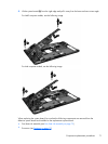
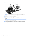
NOTE: Due to the adhesive quality of the thermal material located between the fan/heat sink
assembly and system board components, it might be necessary to move the fan/heat sink
assembly from side to side to detach the assembly.
Component replacement procedures
73