


Removal and replacement procedures 43
To replace the component, reverse the removal procedure.
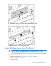
Rear cage
WARNING: To reduce the risk of damage to the midplane and component connectors, always
remove or disengage and extend all blades and power supplies 7.62 cm (3 in) before
removing or installing the rear cage.
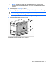
WARNING: To reduce the risk of personal injury or equipment damage, at least two people
are needed to safely move the rear cage.
IMPORTANT: When removing components from the rear cage, note their position for later
replacement.
To remove the component:
1. Power down the server blades ("Power down the server blade" on page 29).
2. Power down the enclosure (on page 30).
3. Disconnect all cables.
4. Disengage and extend the following components approximately 7.62 cm (3 in):
o Half-height and full-height blades ("Half-height or full-height blade" on page 33)
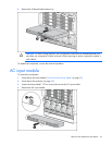
o Power supplies ("HP BladeSystem c7000 power supply or power supply blank" on page 30)
o Power supply blanks ("HP BladeSystem c7000 power supply or power supply blank" on page
30)
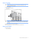
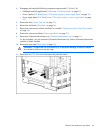
5. Remove the fans ("Active Cool fan" on page 37).
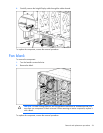
6. Remove the fan blanks ("Fan blank" on page 36).
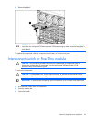
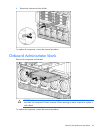
7. Remove the interconnect switches and Pass-Thru modules ("Interconnect switch or Pass-Thru module"
on page 38).
8. Remove the interconnect blanks ("Interconnect blank" on page 37).
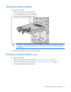
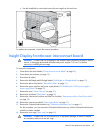
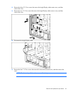
9. Remove the Onboard Administrator tray ("Onboard Administrator tray" on page 41).
For this procedure, you can remove the Onboard Administrator tray with the Onboard Administrator
modules or blanks installed.
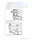
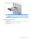
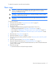
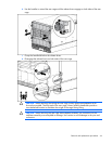
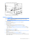
10. Remove the rear cage:
a. Loosen the thumbscrews and open the hinges completely.