


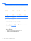
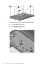
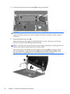

6. Disconnect and remove the camera cable (5) from the system board.
CAUTION: Support the display assembly when removing the following screws. Failure to
support the display assembly can result in damage to the display assembly and other computer
components.
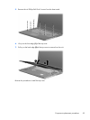
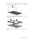
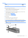
7. Remove the display hinge cover (2).
Release the hinges by removing the six Phillips PM2.5x5.0 screws 1 that secure it to the base
enclosure. First remove the left hinge and then the right.
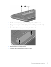
NOTE: On the left side, one of the screws secures a display support strap. On the right side, the
left-most screw secures a ground strap for the wireless cables.
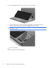
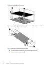
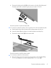
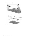
After removing all six screws (1), note that the cables on the hinges (2) may interfere with the
removal of the display. Simply move the panel (3) around the cables and then lift (4). On the
right side, there is a metal plate that you must workaround to remove the display.
58 Chapter 4 Removal and replacement procedures