


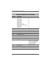

Removal and Replacement Procedures
Maintenance and Service Guide 5–3
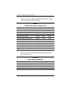
Section Description
# of Screws Removed
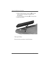
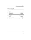
5.4 Hard Drive 2 loosened to remove each
hard drive cover
4 removed to disassemble
each hard drive
5.5 Computer Feet 0
5.6 Memory Module 2 loosened to remove the
memory module compartment
cover
5.7 RTC Battery 0
5.8 Mini Card Module 2
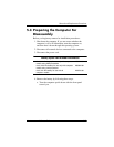
Ä
To prevent an unresponsive system and the display of a
warning message, install only a Mini Card device
authorized for use in your computer by the governmental
agency that regulates wireless devices in your country or
region. If you install a device and then receive a warning
message, remove the device to restore computer
functionality. Then contact technical support by selecting
Start > Help and Support > Contact support.
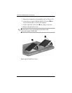
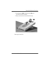
5.9 Optical Drive 1 to remove the optical drive
2 to remove the optical drive
bracket
5.10 Switch Cover 6
5.11 Keyboard 4
5.12 Speaker Assembly 2
5.13 Power Button Board 1
Disassembly Sequence Chart
(Continued)