


Removal and Replacement Procedures
Maintenance and Service Guide 5–79
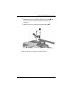
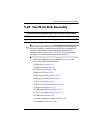
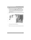
5.25 Fan/Heat Sink Assembly
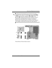
✎
When replacing the fan/heat sink assembly, be sure the display
lid switch module is removed from the defective fan/heat sink
assembly and installed on the replacement fan/heat sink
assembly. Refer to Section 5.22, “Display Lid Switch Module,”
for display lid switch module removal information.
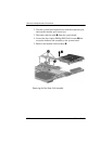
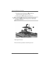
1. Prepare the computer for disassembly (Section 5.3) and
remove the following components:
❏ Hard drive (Section 5.4)
❏ Optical drive (Section 5.9)
❏ Switch cover (Section 5.10)
❏ Keyboard (Section 5.11)
❏ Speaker assembly (Section 5.12)
❏ Display assembly (Section 5.14)
❏ Top cover (Section 5.15)
❏ Wireless switch board (Section 5.16)
❏ Audio board (Section 5.17)
❏ USB/magnetic board (Section 5.19)
❏ Top cover support trim (Section 5.21)
❏ USB board (Section 5.23)
❏ Power connector assembly (Section 5.23)
❏ System board (Section 5.24)
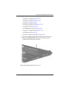
Fan/Heat Sink Assembly Spare Part Number Information
For use only with computer models using Intel processors 434678-001
For use only with computer models using AMD processors 432995-001