


Removal and Replacement Procedures
Maintenance and Service Guide 5–75
❏ Speaker assembly (Section 5.12)
❏ Display assembly (Section 5.14)
❏ Top cover (Section 5.15)
❏ Wireless switch board (Section 5.16)
❏ Audio board (Section 5.17)
❏ USB/magnetic board (Section 5.19)
❏ Top cover support trim (Section 5.21)
❏ USB board (Section 5.23)
❏ Power connector assembly (Section 5.23)
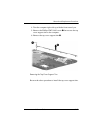
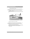
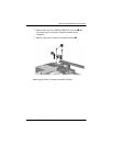
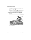
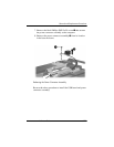
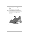
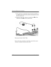
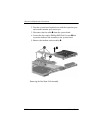
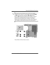
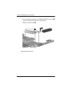
2. Turn the computer upside down with the front toward you.
3. Remove the Phillips PM2.5×8.0 screw that secures the
system board to the base enclosure.
Removing the System Board Screw, Part 1